- Mark as New
- Bookmark
- Subscribe
- Mute
- Subscribe to RSS Feed
- Permalink
- Report Inappropriate Content
Can anyone help me on this ...i would like to use fpga to be used on powerline communication but im blank on how to do it......
Link Copied
- Mark as New
- Bookmark
- Subscribe
- Mute
- Subscribe to RSS Feed
- Permalink
- Report Inappropriate Content
--- Quote Start --- Can anyone help me on this ...i would like to use fpga to be used on powerline communication but im blank on how to do it...... --- Quote End --- You'll need some sort of PHY (physical interface). Go and find out how microcontrollers do it. The interface will be some form of parallel/serial I/O to the PHY, and then the PHY will connect to the power-line. Most likely through an isolating transformer. Google it: http://en.wikipedia.org/wiki/power_line_communication http://www.cypress.com/?id=2330 http://www.maxim-ic.com/datasheet/index.mvp/id/7099 http://www.st.com/internet/imag_video/subclass/923.jsp Cheers, Dave
- Mark as New
- Bookmark
- Subscribe
- Mute
- Subscribe to RSS Feed
- Permalink
- Report Inappropriate Content
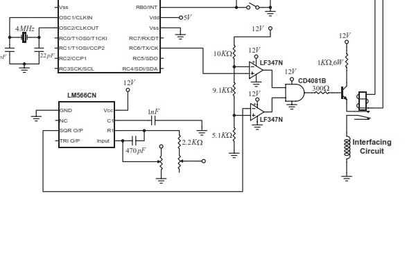
I've found an article on powerlines which uses PIC 16F877A....by any chnce can i knoe which fpga can be compatible to replace PIC 16F877A where it can be used to transmit and receive data....further it can read parallel data and convert it to serial data....ive attached the circuit to be more precise....
- Mark as New
- Bookmark
- Subscribe
- Mute
- Subscribe to RSS Feed
- Permalink
- Report Inappropriate Content
--- Quote Start --- I've found an article on powerlines which uses PIC 16F877A....by any chnce can i knoe which fpga can be compatible to replace PIC 16F877A where it can be used to transmit and receive data....further it can read parallel data and convert it to serial data....ive attached the circuit to be more precise.... --- Quote End --- This is just one method of powerline communications. If you plan on connecting two devices together of your own design, then you can use something like this. However, if you expect to interface to other commercial components, then you have to select a standard PLC interface (there will be multiple). So first, decide what you want to communicate with, then find a compatible PHY. Cheers, Dave
- Mark as New
- Bookmark
- Subscribe
- Mute
- Subscribe to RSS Feed
- Permalink
- Report Inappropriate Content
i would like to use this method ...can u suggest me the right fpga that i can use....and few tutorials sites where i can learn on writing verilog coding for this applications
- Mark as New
- Bookmark
- Subscribe
- Mute
- Subscribe to RSS Feed
- Permalink
- Report Inappropriate Content
--- Quote Start --- i would like to use this method ...can u suggest me the right fpga that i can use.... --- Quote End --- The paper indicates the carrier and data rate: "rectangular waveform with frequency of 140 KHz which is much greater than the used data baud rate (500 bit/s)" So literally any FPGA can be used. --- Quote Start --- and few tutorials sites where i can learn on writing verilog coding for this applications --- Quote End --- Use Google. Use the tutorials that come with Modelsim, Quartus, and the University program code. Cheers, Dave
- Mark as New
- Bookmark
- Subscribe
- Mute
- Subscribe to RSS Feed
- Permalink
- Report Inappropriate Content
...if any fpga can be used ... i have a DE2 board which consist cyclone 2 ...can i use the board to test the likewise circuit..Any idea how the circuit looks like if i want to replace the PIC....Any suggestion on how can i write my coding as i am using verilog to do it.....
thnx Alen:)- Mark as New
- Bookmark
- Subscribe
- Mute
- Subscribe to RSS Feed
- Permalink
- Report Inappropriate Content
--- Quote Start --- i have a DE2 board which consist cyclone 2 ...can i use the board to test the likewise circuit.. --- Quote End --- That would meet the requirement of 'any FPGA board'. --- Quote Start --- Any idea how the circuit looks like if i want to replace the PIC.... --- Quote End --- Look at the PIC circuit. Make sure you protect the FPGA I/O. Check that voltages are compatible. Add buffers where they are not. Simulate the analog circuit using LTSpice. Try something out. If you use a buffer board between your DE2 and your test circuits, then the worst you can do is destroy the buffer board. Its time to roll up your sleeves and do something :) Cheers, Dave
- Mark as New
- Bookmark
- Subscribe
- Mute
- Subscribe to RSS Feed
- Permalink
- Report Inappropriate Content
how can i come across for the verilog coding as i am using the de-2 board ...how can i manipulate the rs232 pin to be the transmitter...
--- Quote Start --- Try something out. If you use a buffer board between your DE2 and your test circuits, then the worst you can do is destroy the buffer board --- Quote End --- and what type of buffer board can i prepare for this...- Mark as New
- Bookmark
- Subscribe
- Mute
- Subscribe to RSS Feed
- Permalink
- Report Inappropriate Content
--- Quote Start --- how can i come across for the verilog coding as i am using the de-2 board ...how can i manipulate the rs232 pin to be the transmitter... --- Quote End --- Write a UART routine, or create an SOPC or Qsys System with a NIOS processor and include a UART in that system. --- Quote Start --- and what type of buffer board can i prepare for this... --- Quote End --- Sparkfun and other sites have buffer boards with LS244/LS245 style buffers. Its really up to whatever your design requires. If you need high current drivers, then you might need a boost transistor. Look in an electronics book. Cheers, Dave
- Mark as New
- Bookmark
- Subscribe
- Mute
- Subscribe to RSS Feed
- Permalink
- Report Inappropriate Content
I am going to build this part of the project which is the OOK modulator as shown
belowhttps://www.alteraforum.com/forum/attachment.php?attachmentid=5226 and i have to interface it with a another board using RS232 male connector soe that i can attach to my DE-2 board... by exactly following the circuit can i connect to the RS232 port in my DE-2 would it work?...ive tried using LT spice for simulation purposes since im not that good on using the software i found it hard to come up with the simulation ...i am preparin to do it practically... and i have found a RS232 based verilog code in order to be test for the Tx and Rx...can this coding work for this powerline project...im connecting two ALTERA DE-2 boards using the powerline....any advise...// RS-232 TX module
//`define DEBUG // in DEBUG mode, we output one bit per clock cycle (useful for faster simulations)
module async_transmitter(clk, TxD_start, TxD_data, TxD, TxD_busy);
input clk, TxD_start;
input TxD_data;
output TxD, TxD_busy;
parameter ClkFrequency = 25000000; // 25MHz
parameter Baud = 115200;
parameter RegisterInputData = 1; // in RegisterInputData mode, the input doesn't have to stay valid while the character is been transmitted
// Baud generator
parameter BaudGeneratorAccWidth = 16;
reg BaudGeneratorAcc;
`ifdef DEBUG
wire BaudGeneratorInc = 17'h10000;
`else
wire BaudGeneratorInc = ((Baud<<(BaudGeneratorAccWidth-4))+(ClkFrequency>>5))/(ClkFrequency>>4);
`endif
wire BaudTick = BaudGeneratorAcc;
wire TxD_busy;
always @(posedge clk) if(TxD_busy) BaudGeneratorAcc <= BaudGeneratorAcc + BaudGeneratorInc;
// Transmitter state machine
reg state;
wire TxD_ready = (state==0);
assign TxD_busy = ~TxD_ready;
reg TxD_dataReg;
always @(posedge clk) if(TxD_ready & TxD_start) TxD_dataReg <= TxD_data;
wire TxD_dataD = RegisterInputData ? TxD_dataReg : TxD_data;
always @(posedge clk)
case(state)
4'b0000: if(TxD_start) state <= 4'b0001;
4'b0001: if(BaudTick) state <= 4'b0100;
4'b0100: if(BaudTick) state <= 4'b1000; // start
4'b1000: if(BaudTick) state <= 4'b1001; // bit 0
4'b1001: if(BaudTick) state <= 4'b1010; // bit 1
4'b1010: if(BaudTick) state <= 4'b1011; // bit 2
4'b1011: if(BaudTick) state <= 4'b1100; // bit 3
4'b1100: if(BaudTick) state <= 4'b1101; // bit 4
4'b1101: if(BaudTick) state <= 4'b1110; // bit 5
4'b1110: if(BaudTick) state <= 4'b1111; // bit 6
4'b1111: if(BaudTick) state <= 4'b0010; // bit 7
4'b0010: if(BaudTick) state <= 4'b0011; // stop1
4'b0011: if(BaudTick) state <= 4'b0000; // stop2
default: if(BaudTick) state <= 4'b0000;
endcase
// Output mux
reg muxbit;
always @( * )
case(state)
3'd0: muxbit <= TxD_dataD;
3'd1: muxbit <= TxD_dataD;
3'd2: muxbit <= TxD_dataD;
3'd3: muxbit <= TxD_dataD;
3'd4: muxbit <= TxD_dataD;
3'd5: muxbit <= TxD_dataD;
3'd6: muxbit <= TxD_dataD;
3'd7: muxbit <= TxD_dataD;
endcase
// Put together the start, data and stop bits
reg TxD;
always @(posedge clk) TxD <= (state<4) | (state & muxbit); // register the output to make it glitch free
endmodule and the receiver part // RS-232 RX module
module async_receiver(clk, RxD, RxD_data_ready, RxD_data, RxD_endofpacket, RxD_idle);
input clk, RxD;
output RxD_data_ready; // onc clock pulse when RxD_data is valid
output RxD_data;
parameter ClkFrequency = 25000000; // 25MHz
parameter Baud = 115200;
// We also detect if a gap occurs in the received stream of characters
// That can be useful if multiple characters are sent in burst
// so that multiple characters can be treated as a "packet"
output RxD_endofpacket; // one clock pulse, when no more data is received (RxD_idle is going high)
output RxD_idle; // no data is being received
// Baud generator (we use 8 times oversampling)
parameter Baud8 = Baud*8;
parameter Baud8GeneratorAccWidth = 16;
wire Baud8GeneratorInc = ((Baud8<<(Baud8GeneratorAccWidth-7))+(ClkFrequency>>8))/(ClkFrequency>>7);
reg Baud8GeneratorAcc;
always @(posedge clk) Baud8GeneratorAcc <= Baud8GeneratorAcc + Baud8GeneratorInc;
wire Baud8Tick = Baud8GeneratorAcc;
////////////////////////////
reg RxD_sync_inv;
always @(posedge clk) if(Baud8Tick) RxD_sync_inv <= {RxD_sync_inv, ~RxD};
// we invert RxD, so that the idle becomes "0", to prevent a phantom character to be received at startup
reg RxD_cnt_inv;
reg RxD_bit_inv;
always @(posedge clk)
if(Baud8Tick)
begin
if( RxD_sync_inv && RxD_cnt_inv!=2'b11) RxD_cnt_inv <= RxD_cnt_inv + 2'h1;
else
if(~RxD_sync_inv && RxD_cnt_inv!=2'b00) RxD_cnt_inv <= RxD_cnt_inv - 2'h1;
if(RxD_cnt_inv==2'b00) RxD_bit_inv <= 1'b0;
else
if(RxD_cnt_inv==2'b11) RxD_bit_inv <= 1'b1;
end
reg state;
reg bit_spacing;
// "next_bit" controls when the data sampling occurs
// depending on how noisy the RxD is, different values might work better
// with a clean connection, values from 8 to 11 work
wire next_bit = (bit_spacing==4'd10);
always @(posedge clk)
if(state==0)
bit_spacing <= 4'b0000;
else
if(Baud8Tick)
bit_spacing <= {bit_spacing + 4'b0001} | {bit_spacing, 3'b000};
always @(posedge clk)
if(Baud8Tick)
case(state)
4'b0000: if(RxD_bit_inv) state <= 4'b1000; // start bit found?
4'b1000: if(next_bit) state <= 4'b1001; // bit 0
4'b1001: if(next_bit) state <= 4'b1010; // bit 1
4'b1010: if(next_bit) state <= 4'b1011; // bit 2
4'b1011: if(next_bit) state <= 4'b1100; // bit 3
4'b1100: if(next_bit) state <= 4'b1101; // bit 4
4'b1101: if(next_bit) state <= 4'b1110; // bit 5
4'b1110: if(next_bit) state <= 4'b1111; // bit 6
4'b1111: if(next_bit) state <= 4'b0001; // bit 7
4'b0001: if(next_bit) state <= 4'b0000; // stop bit
default: state <= 4'b0000;
endcase
reg RxD_data;
always @(posedge clk)
if(Baud8Tick && next_bit && state) RxD_data <= {~RxD_bit_inv, RxD_data};
reg RxD_data_ready, RxD_data_error;
always @(posedge clk)
begin
RxD_data_ready <= (Baud8Tick && next_bit && state==4'b0001 && ~RxD_bit_inv); // ready only if the stop bit is received
RxD_data_error <= (Baud8Tick && next_bit && state==4'b0001 && RxD_bit_inv); // error if the stop bit is not received
end
reg gap_count;
always @(posedge clk) if (state!=0) gap_count<=5'h00; else if(Baud8Tick & ~gap_count) gap_count <= gap_count + 5'h01;
assign RxD_idle = gap_count;
reg RxD_endofpacket; always @(posedge clk) RxD_endofpacket <= Baud8Tick & (gap_count==5'h0F);
endmodule
- Mark as New
- Bookmark
- Subscribe
- Mute
- Subscribe to RSS Feed
- Permalink
- Report Inappropriate Content
--- Quote Start --- ive tried using LT spice for simulation purposes since im not that good on using the software i found it hard to come up with the simulation ...i am preparin to do it practically... --- Quote End --- What is harder; learning how to use software (LTSpice), or watching your hardware go up in smoke? The Yahoo LTSpice has lots of helpful users. --- Quote Start --- ....any advise... --- Quote End --- Learn how to use Modelsim and simulate the Verilog. Its pointless asking others to read code that you just 'found' on the internet. Show that you have made an effort to try to understand and test the code first, and then people will be more willing to help you when you have problems. Otherwise, your question just comes across as being lazy; "its too hard, can someone else please do this for me?". Try and put some effort in first. Cheers, Dave
- Subscribe to RSS Feed
- Mark Topic as New
- Mark Topic as Read
- Float this Topic for Current User
- Bookmark
- Subscribe
- Printer Friendly Page