- Mark as New
- Bookmark
- Subscribe
- Mute
- Subscribe to RSS Feed
- Permalink
- Report Inappropriate Content
Hi, I successfully start a 10g PHY ip in way that i can receive the packet. Now I’ve been trying to configure 40g PHY without mac just to get any changes of data at IP output and I can’t achieve that.
In “ug_arria10_xcvr_phy.pdf” table 8 I found that this IP handles 40GBASE-R with “Basic (Enhanced PCS)” Transceiver Configuration Rule, and “Low Latency EnhancedPCS” in protocol preset. As annotation below the table says, I configured 4 channels. I also followed all steps in chapter “How to Enable Low Latency in Basic Enhanced PCS”(64b to 66b) and enabled RX and TX scramblers without errors in designer.
If now I simulate this IP core I’m getting constant “0100009C0100009C” (similar tb for 10g gives idle “07”) , ‘hi’ on “lockedtoref” and “lockedtodata” and ‘low’ on block_lock at output. If I test this on hardware with Signaltap I receive “0100009C0100009C” mixed with “fefefefefefefefe”, as if connection was established for short time but some error occurs.
What I am doing wrong? Is there any more documentation about 40g only? I attached configured IP.
Link Copied
- Mark as New
- Bookmark
- Subscribe
- Mute
- Subscribe to RSS Feed
- Permalink
- Report Inappropriate Content
- Mark as New
- Bookmark
- Subscribe
- Mute
- Subscribe to RSS Feed
- Permalink
- Report Inappropriate Content
Let's focus on simulation which i think is failing too. My PHY 10g simulation test was to loopback TX to RX serial data, while set "0707070707070707" 'idle' state on parallel TX input, after tx_ready and rx_ready signals goes '1'. Lockedtoref and lockedtodat goes '1', parallel RX output changes from “0100009C0100009C” to "0707070707070707" 'idle' state (test pass).
When I trying to do same test on PHY 4x10g IP configured as described in first post, the parallel RX output stays constant “0100009C0100009C” while tx_ready, rx_ready, lockedtoref and lockedtodat goes '1' (every channel similarly). Mo matter what i put on parallel TX input, output doesn’t change.
- Mark as New
- Bookmark
- Subscribe
- Mute
- Subscribe to RSS Feed
- Permalink
- Report Inappropriate Content
HI,
I have been working on some digging and found out "0100009C" represent local fault signaling. (refer to attachment)
Did you implement reconciliation sublayer (RS) to handle local and remote fault ?
Some of the causes of local fault that I can think of is like below
- transceiver not lock or stuck in reset - shouldn't be your case here
- your 40G design (4 x 10G) PCS channel alignment word lock or block lock operation is not completed yet you already blast out Tx data traffic - my highest suspect
- high BER on channel link - unlikely as you are running sim
- PCS internal FIFO overflow/underflow - shouldn't be your case also
Thanks.
Regards,
dlim
- Mark as New
- Bookmark
- Subscribe
- Mute
- Subscribe to RSS Feed
- Permalink
- Report Inappropriate Content


Hi, according to what you describe in second point in post above – I am only putting “0100009C” or “0200009C” before “block lock” and” rx data” change to IDLE state (x“07”), same as in my 10g testbench(10G works,40g not work). I attached two screen shots from this testbench.
When I studying LL40G PHY&MAC example I found file with PHY configuration for 4x10G xcvr_native_a10 and its not configured as described in first post (from “ug_arria10_xcvr_phy.pdf”). I attached this two files in zip to easy compare in any comparing tool.
Should I use this configuration from LL40g?
- Mark as New
- Bookmark
- Subscribe
- Mute
- Subscribe to RSS Feed
- Permalink
- Report Inappropriate Content
Hi EEnam,
I looked at your sim waveform. 0100009C value appeared on XGmii interface but Intel FPGA NativePHY IP doesn't has XGmii interface. It only contains the transceiver channel tx_parallel_data or rx_parallel_date to/from FPGA core logic.
- I believe transceiver data output to XGmii interface conversion is done by your own IP design logic, right ? Have you isolate the problem is on transceiver data output or on XGmii interface conversion logic itself ? You may want to cross check your design again
- Then other thing that I checked with you earlier was did you implement reconciliation sublayer (RS) to handle local and remote fault as "0100009C" represent local fault signaling ?
- Finally regarding transceiver channel setting difference btw 10G NativePHY ip preset vs LL 40G Ethernet MAC + PHY IP
- There is no hard rule on how to implement the PHY design logic. It's really up to IP developer on how they want to implement the design
- 10G NativePHY ip preset use 64 bits width data output to FPGA core logic while enable certain hard PCS function in transceiver channel
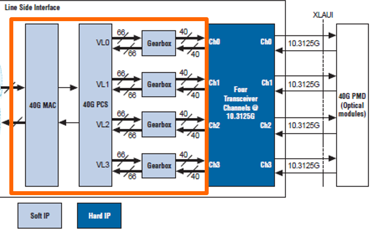
- LL 40G Ethernet MAC + PHY IP on the other hand use 40 bits width data output to FPGA core logic while most of the PCS function is created in FPGA core logic instead of using hard PCS function in transceiver channel. Unfortunately how the IP developer build the whole 40G PHY design is proprietary info by Intel. (attached is high level block diagram of 40G Eth IP)
My debug suggestion is you may want to cross check your XGmii interface conversion logic design again.
Also does it make a difference if you generate other input value (not 0100009C) to xgmii_tx_data ?
Typically Intel doesn't just simulate Ethernet PHY only. Our example design always come with both Ethernet MAC and PHY together.
Thanks.
Regards,
dlim
- Mark as New
- Bookmark
- Subscribe
- Mute
- Subscribe to RSS Feed
- Permalink
- Report Inappropriate Content
Hi dlim.
“xgmii" signals names is inherited from my 10G test where parallel data(64b) and control signals(8 bit) forms xgmii standard signals right from NativePHY IP. In 4x10g there is only 256b parallel data and 8b control signals which are split to my signals named “xgmii”.In conclusion - it's same data that I am getting on parallel output of NativePHY IP.
I implemented simple reconciliation logic based at 10g which is sending 0x9c000002 on tx when local fault detect or idle “0x07..” when remote fault detected (ug_32b_10g_ethernet_mac.pdf, page 58, XGMII Error Handling (Link Fault) ).
No matter what I put on tx data input, output of NativePHY IP in my 4x10G config is stuck at local fault. I was expecting at least random values after 'hi' on rx_ready and pushing random data on tx but nothing change. There is a difference only when I put ‘X’ on tx data because then serial is not generated and rx_ready fall to low.
- Mark as New
- Bookmark
- Subscribe
- Mute
- Subscribe to RSS Feed
- Permalink
- Report Inappropriate Content
- Mark as New
- Bookmark
- Subscribe
- Mute
- Subscribe to RSS Feed
- Permalink
- Report Inappropriate Content

Yes, you are right, “qsfp” signals in screen above is direct output from transceiver and rx-tx is looped in logic. I modify arrays names and control signals assignments for better clarity.
Only thing that is strange to me is that control signals is indicating data transfer (https://www.intel.com/content/dam/www/programmable/us/en/pdfs/literature/hb/arria-10/ug_arria10_xcvr_phy.pdf page 83, Table 60) when I think this is control word (http://www.ieee802.org/3/ak/public/jan03/WPcls48_1_0.pdf Table 48–2).
Apart from that, the control and data signals are just looped so it should work anyway.
- Mark as New
- Bookmark
- Subscribe
- Mute
- Subscribe to RSS Feed
- Permalink
- Report Inappropriate Content
Hi EEnam,
are you using Quartus Pro? I'm observing similiar behaviour after migrating to Quartus 19.1 Pro. On Quartus Standard 18.1 It was working on hardware. Now I get remote faults, local, faults from phy. Signals blk_lock and lockedtodata are high together with highber.
- Mark as New
- Bookmark
- Subscribe
- Mute
- Subscribe to RSS Feed
- Permalink
- Report Inappropriate Content
Hi SSilu,
I suspect your case is different from EEnam. He is running sim not hardware testing, so there is no concern from signal integrity perspective.
For your case, hardware testing with high BER is bad. You want to confirm nothing wrong with your board setup/design that may impact signal integrity.
If you confirm board side is good then you can switch to debug Quartus design.
- You can cross check the transceiver PMA analog setting between v18.1 and v19.1 design to check for potential setting mismatch
- Else you can also start to build the design from scratch in v19.1 to ensure there is no design files corruption during Quartus design upgrade from v18.1 to v19.1
Thanks.
Regards,
dlim
- Mark as New
- Bookmark
- Subscribe
- Mute
- Subscribe to RSS Feed
- Permalink
- Report Inappropriate Content
Yes my case is different. It's strange but Quartus Pro 19.1 requires different settings for PMA than Quartus standard 18.1. I'm not sure this because of standard -> pro migration or maybe version 18.1 to 19.1 increment. However those are settings I used on my DE5A-net board to make qsfp work. I probably should have run some transceiver toolkit to adjust them, but I tried some random changes (based on DE5A-net evaluation bard examples) and it works so far:
    # Rx
    set_instance_assignment -name XCVR_A10_RX_LINK LR -to QSFPA_RX_p[0]
    set_instance_assignment -name XCVR_A10_RX_TERM_SEL R_R1 -to QSFPA_RX_p[0]
    set_instance_assignment -name XCVR_VCCR_VCCT_VOLTAGE 1_0V -to QSFPA_RX_p[0]
    # Tx
    set_instance_assignment -name XCVR_A10_TX_LINK LR -to QSFPA_TX_p[0]
    set_instance_assignment -name XCVR_A10_TX_TERM_SEL R_R1 -to QSFPA_TX_p[0]
    set_instance_assignment -name XCVR_VCCR_VCCT_VOLTAGE 1_0V -to QSFPA_TX_p[0]
    # Clock
    set_instance_assignment -name XCVR_A10_REFCLK_TERM_TRISTATE TRISTATE_OFF -to QSFPA_REFCLK_p

#tx: vod control, 28
set_instance_assignment -name XCVR_A10_TX_VOD_OUTPUT_SWING_CTRL 28 -to QSFPA_TX_p[0]
#tx: pre-emphasis first post-tap, -7
set_instance_assignment -name XCVR_A10_TX_PRE_EMP_SIGN_1ST_POST_TAP FIR_POST_1T_NEG -to QSFPA_TX_p[0]
set_instance_assignment -name XCVR_A10_TX_PRE_EMP_SWITCHING_CTRL_1ST_POST_TAP 7 -to QSFPA_TX_p[0]
#tx: pre-emphasis pre-tap, -2
set_instance_assignment -name XCVR_A10_TX_PRE_EMP_SIGN_PRE_TAP_1T FIR_PRE_1T_NEG -to QSFPA_TX_p[0]
set_instance_assignment -name XCVR_A10_TX_PRE_EMP_SWITCHING_CTRL_PRE_TAP_1T 2 -to QSFPA_TX_p[0]
#rx: DC gain(0~4), 4
set_instance_assignment -name XCVR_A10_RX_EQ_DC_GAIN_TRIM NO_DC_GAIN -to QSFPA_RX_p[0]
#EqControl(0~28) = 15
set_instance_assignment -name XCVR_A10_RX_ADP_CTLE_ACGAIN_4S RADP_CTLE_ACGAIN_4S_28 -to QSFPA_RX_p[0]
#rx: VGA(0~7) = 7
set_instance_assignment -name XCVR_A10_RX_ADP_VGA_SEL RADP_VGA_SEL_7 -to QSFPA_RX_p[0]
# ?
set_instance_assignment -name XCVR_A10_RX_ADP_CTLE_EQZ_1S_SEL RADP_CTLE_EQZ_1S_SEL_7 -to QSFPA_RX_p[0]
# ?
set_instance_assignment -name XCVR_A10_RX_ADP_DFE_FXTAP1 RADP_DFE_FXTAP1_63 -to QSFPA_RX_p[0]
# ?
set_instance_assignment -name XCVR_A10_RX_ONE_STAGE_ENABLE NON_S1_MODE -to QSFPA_RX_p[0]
- Subscribe to RSS Feed
- Mark Topic as New
- Mark Topic as Read
- Float this Topic for Current User
- Bookmark
- Subscribe
- Printer Friendly Page