- Mark as New
- Bookmark
- Subscribe
- Mute
- Subscribe to RSS Feed
- Permalink
- Report Inappropriate Content
Hello
I am using the Altera Megacore NCO Compiler and need to dinamically adjust the phase of the generated sine wave. The core has an input called phase_mod_i[] which is used for this purpose. The problem is that I don't know the relation between the desired phase adjust (in degrees) and the number I need to input in the core. Is it linear? As in: Input (with 15 bits of angular precision) / Phase Difference (degrees) 000000000000000 / 0 100000000000000 / 180 111111111111111 / 360 (or 0) Can anyone help me please? Thank you ThiagoLink Copied
- Mark as New
- Bookmark
- Subscribe
- Mute
- Subscribe to RSS Feed
- Permalink
- Report Inappropriate Content
Build a (small) NCO. Simulate it in quartus. Set input words to 0 except the phase modulation input, which you put a count sequnce on (thats the reason I wrote small!), and you will see how it works. Thats the way I would go about... after skimming the manual of course.
My guess is that 100000000..0 is -pi and 0111111111..1 is almost pi, ie. twos complement But the simulations will tell.- Mark as New
- Bookmark
- Subscribe
- Mute
- Subscribe to RSS Feed
- Permalink
- Report Inappropriate Content
Hi Larsen
Thanks for the idea :) I've set up the simulation and the results are attached to this message. The bottom sine wave is the reference so it isn't changed by the phase increment. I've placed some time bars to help to identify the phase change between the reference and the test sine wave. Thiago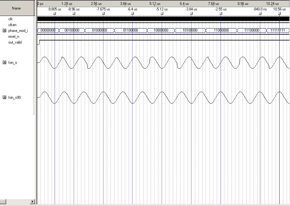
- Mark as New
- Bookmark
- Subscribe
- Mute
- Subscribe to RSS Feed
- Permalink
- Report Inappropriate Content
that wasn't exactly what I meant. You should also put phi_inc_i=0. This removes the time dependence of the phase in the accumulator (integrator part if you prefer). In that way you will see exactly what is the contribution to the output for a given phase_mod value.
My investigation seems to confirm the Pi=1000...0. Dont be fooled by the delay through the core when reading the output value which is the result of the input. And do remember to switch the dither off! Good luck.- Mark as New
- Bookmark
- Subscribe
- Mute
- Subscribe to RSS Feed
- Permalink
- Report Inappropriate Content
Hi Larsen
I did keep the phase_inc_i value constant, so the changes we see are from the phase_mod_i exclusively. In the test I had two NCO in parallel with the same inputs, except for the phase_mod_i which was constant=0 in the reference NCO. Thiago- Mark as New
- Bookmark
- Subscribe
- Mute
- Subscribe to RSS Feed
- Permalink
- Report Inappropriate Content
Thiago,
phi_inc_i should be constant zero, in order to eliminate the phase incrementing as time clocks by. phi_inc_i is the frequency and you want that to be zero. In this way the object of your study, as I understood your question, the phase_mod_i[] is the sole contributor to the output, improving tremendously the visiblity. Clear? If not, ask again. henning- Mark as New
- Bookmark
- Subscribe
- Mute
- Subscribe to RSS Feed
- Permalink
- Report Inappropriate Content
- Mark as New
- Bookmark
- Subscribe
- Mute
- Subscribe to RSS Feed
- Permalink
- Report Inappropriate Content
if you read equation 2 on page 37 in nco manual (7.1version): fo=0, fFm=0 fiDither=0, only fiPM=phi_mod_i remains as a phase contribution, so the phase no longer advances with time (clock) factor nT. But you can basically see the answer to your original question from your simulation that a phase_mod_i=10000..0 is pi because sin(0)=sin(pi)=sin(-pi)=0. The value for phase_mod_i=1111111...11 and any other values for that matter, should be easy to read off your simulation as well but it is not visible on your dump. Equation (2) shows that it is linear. Does'nt that answer your original question?
- Mark as New
- Bookmark
- Subscribe
- Mute
- Subscribe to RSS Feed
- Permalink
- Report Inappropriate Content
--- Quote Start --- Hello I am using the Altera Megacore NCO Compiler and need to dinamically adjust the phase of the generated sine wave. The core has an input called phase_mod_i[] which is used for this purpose. The problem is that I don't know the relation between the desired phase adjust (in degrees) and the number I need to input in the core. Is it linear? As in: Input (with 15 bits of angular precision) / Phase Difference (degrees) 000000000000000 / 0 100000000000000 / 180 111111111111111 / 360 (or 0) Can anyone help me please? Thank you Thiago --- Quote End --- Hi, i'm a student university and i made a QPSK modulator with Altera Stratix II and i don't understand how set NCO for an phase modulation and how define the constallation mapper.... thx for support
- Mark as New
- Bookmark
- Subscribe
- Mute
- Subscribe to RSS Feed
- Permalink
- Report Inappropriate Content
--- Quote Start --- Hi, i'm a student university and i made a QPSK modulator with Altera Stratix II and i don't understand how set NCO for an phase modulation and how define the constallation mapper.... thx for support --- Quote End --- The steps for qpsk are: get your data bits(0,1) as pairs map pairs to two separate I,Q streams (as +1/-1) shape the pulses but I assume this step is too much for Uni student so ignore it multiply each of I,Q streams by cos/sin in a complex multiplier(mixer) The output of multiplier will be the modulated qpsk (centerd on your chosen nco frequency) The +1/-1 will simply invert or leave the phase of your cos/sin (0 or 180 degrees)
- Mark as New
- Bookmark
- Subscribe
- Mute
- Subscribe to RSS Feed
- Permalink
- Report Inappropriate Content
--- Quote Start --- The steps for qpsk are: get your data bits(0,1) as pairs map pairs to two separate I,Q streams (as +1/-1) shape the pulses but I assume this step is too much for Uni student so ignore it multiply each of I,Q streams by cos/sin in a complex multiplier(mixer) The output of multiplier will be the modulated qpsk (centerd on your chosen nco frequency) The +1/-1 will simply invert or leave the phase of your cos/sin (0 or 180 degrees) --- Quote End --- ok thx, now i have done approximately an schematic in simulink, but i don't sure on the first part on bit mapping and how "teach" at the NCO how change the phase... However i attach my schematic...
- Mark as New
- Bookmark
- Subscribe
- Mute
- Subscribe to RSS Feed
- Permalink
- Report Inappropriate Content
--- Quote Start --- ok thx, now i have done approximately an schematic in simulink, but i don't sure on the first part on bit mapping and how "teach" at the NCO how change the phase... However i attach my schematic... --- Quote End --- just multiply stream by sin/cos. +1* nco output = nco output -1* nco output = - nco output
- Subscribe to RSS Feed
- Mark Topic as New
- Mark Topic as Read
- Float this Topic for Current User
- Bookmark
- Subscribe
- Printer Friendly Page