- Mark as New
- Bookmark
- Subscribe
- Mute
- Subscribe to RSS Feed
- Permalink
- Report Inappropriate Content
implemented the module according to manual i was able to run the program successfully but i am not able to find the output
may be i assigned the pins in wrong way can anyone suggest me to which pin i should assign the following adc_sclk and adc saddr , adc cs and adc sdat thank youLink Copied
- Mark as New
- Bookmark
- Subscribe
- Mute
- Subscribe to RSS Feed
- Permalink
- Report Inappropriate Content
Hi Maheshbimaq,
1.In signaltap are you able to see the input signal? Check the input source. 2.In signaltap have you set trigger conditions? 3.ADC_SCK PIN_V10, ADC_SDO PIN_AD4, ADC_SDI PIN_AC4 & ADC_CONVST PIN_U9. Best Regards, Anand Raj Shankar (This message was posted on behalf of Intel Corporation)- Mark as New
- Bookmark
- Subscribe
- Mute
- Subscribe to RSS Feed
- Permalink
- Report Inappropriate Content
--- Quote Start --- implemented the module according to manual i was able to run the program successfully but i am not able to find the output may be i assigned the pins in wrong way can anyone suggest me to which pin i should assign the following adc_sclk and adc saddr , adc cs and adc sdat thank you --- Quote End --- This depends on what board you are using. Refer to the manual provided by the manufacturer (likely Terasic). They list all the FPGA pin connections for on-board devices.
- Mark as New
- Bookmark
- Subscribe
- Mute
- Subscribe to RSS Feed
- Permalink
- Report Inappropriate Content
thank you for your reply!
do i need to set this trigger condition after i mount my output file(sof) on FPGA? can you tell me how to set the trigger condition because i am new to this tool and do you have any material for this so that i can learn- Mark as New
- Bookmark
- Subscribe
- Mute
- Subscribe to RSS Feed
- Permalink
- Report Inappropriate Content
i have done the pin assignment correctly the problem is i am not able to set the trigger condition i dont have any experience with this tool so it will be easier for me if have any manual or steps to follow
so please could you help me- Mark as New
- Bookmark
- Subscribe
- Mute
- Subscribe to RSS Feed
- Permalink
- Report Inappropriate Content
Hi
Go through the user guide of signal-tap for more information also check the below links https://www.youtube.com/watch?v=llodw5in4pg https://www.altera.com/support/training/course/odsw1171.html https://www.youtube.com/watch?v=vhkzxcexuaa Can you attach your observed output window image. Best Regards, Anand Raj Shankar (This message was posted on behalf of Intel Corporation)- Mark as New
- Bookmark
- Subscribe
- Mute
- Subscribe to RSS Feed
- Permalink
- Report Inappropriate Content
https://www.alteraforum.com/forum/attachment.php?attachmentid=14506
so in was able to see my nodes on analyzer....can you suggest me which condition should i give to see the output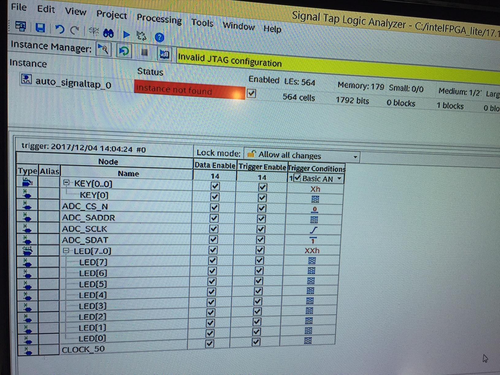
- Mark as New
- Bookmark
- Subscribe
- Mute
- Subscribe to RSS Feed
- Permalink
- Report Inappropriate Content
Hi,
Understand the hardware and user manual. Trigger on the clock at which ADC Data is changing/sampling. or trigger the data itself(led(0..7)) for checking it. Best Regards, Anand Raj Shankar (This message was posted on behalf of Intel Corporation)- Mark as New
- Bookmark
- Subscribe
- Mute
- Subscribe to RSS Feed
- Permalink
- Report Inappropriate Content
https://www.alteraforum.com/forum/attachment.php?attachmentid=14519
i want to read a analog input on 2*5 adc header i followed the module ....in the manual it says use pot (variable resistor) and it says run test.bat file but when i do it shows some value from channel 7 but i have connected to channel 0 of adc or can you tell me if i am going wrong ?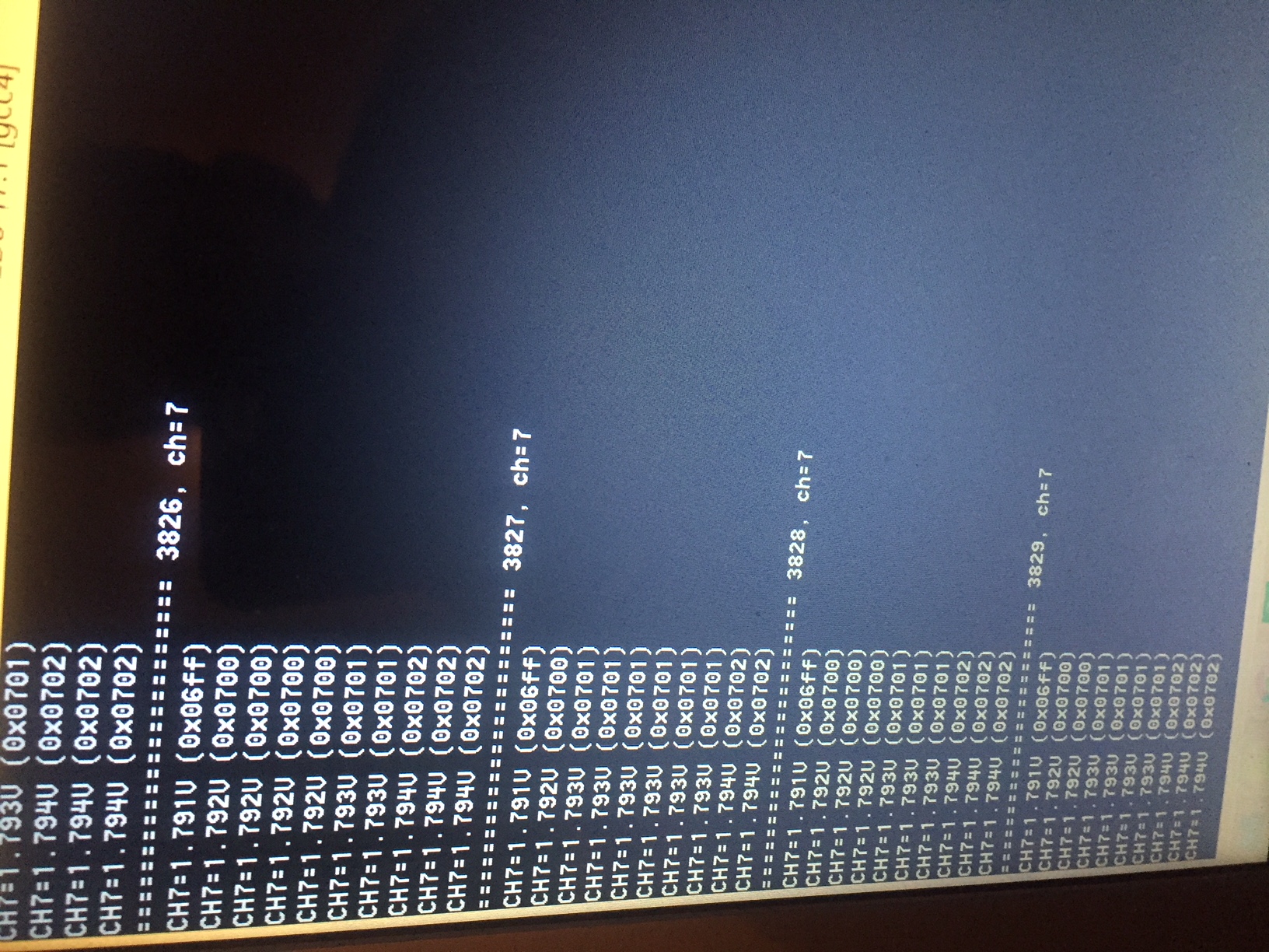
- Mark as New
- Bookmark
- Subscribe
- Mute
- Subscribe to RSS Feed
- Permalink
- Report Inappropriate Content
my question is how do i change it to channel 0
?- Mark as New
- Bookmark
- Subscribe
- Mute
- Subscribe to RSS Feed
- Permalink
- Report Inappropriate Content
Hi
Have you "Set SW[2:0] = 000, to measure channel 0 of ADC"? Best Regards, Anand Raj Shankar (This message was posted on behalf of Intel Corporation)- Mark as New
- Bookmark
- Subscribe
- Mute
- Subscribe to RSS Feed
- Permalink
- Report Inappropriate Content
successfully done with ADC part!!
i have one more question is it possible to read a analog output on GPIO by connecting additional circuitary (DAC) for example i want to apply analog signal on 2*5 adc header and read that on GPIO is it possible? thank you Mahesh- Mark as New
- Bookmark
- Subscribe
- Mute
- Subscribe to RSS Feed
- Permalink
- Report Inappropriate Content
--- Quote Start --- successfully done with ADC part!! i have one more question is it possible to read a analog output on GPIO by connecting additional circuitary (DAC) for example i want to apply analog signal on 2*5 adc header and read that on GPIO is it possible? thank you Mahesh --- Quote End --- Yes, you can use additional circuitry. While selecting DAC circuitry take care on LSB/Resolution of DAC and GPIO capability.(i.e Whether you can detect the LSB change?) Best Regards, Anand Raj Shankar (This message was posted on behalf of Intel Corporation)
- Mark as New
- Bookmark
- Subscribe
- Mute
- Subscribe to RSS Feed
- Permalink
- Report Inappropriate Content
is there any example related to this where i can understand something and implement ?
and i am planning to use ic ad421 which is a dac ( external circuit )to convert digital signal on gpio to analog- Mark as New
- Bookmark
- Subscribe
- Mute
- Subscribe to RSS Feed
- Permalink
- Report Inappropriate Content
ADC IS 12BIT resolution which is inbuilt so
reading an input signal on 2*5 header is done ! how can i read the same analog signal on GPIO? just similar to connecting to leds on board ? or there is any other technique or should i use pwm? if there are any example it will help me alot- Mark as New
- Bookmark
- Subscribe
- Mute
- Subscribe to RSS Feed
- Permalink
- Report Inappropriate Content
Hi,
1.You should have DAC resolution of at least 12 or greater is better keeping verf in consideration and also the driving strength. 2.Chose a board/Design like that, You can find the some martials from terasic for other board/daughter boards which will help you to understand requirements for your board. Check the board below http://www.terasic.com.tw/cgi-bin/page/archive.pl?language=english&categoryno=67&no=278 https://www.altera.com/content/dam/altera-www/global/en_us/portal/dsn/42/doc-us-dsnbk-42-5008051605255-d8m-gpio-user-manual.pdf Best Regards, Anand Raj Shankar (This message was posted on behalf of Intel Corporation)- Subscribe to RSS Feed
- Mark Topic as New
- Mark Topic as Read
- Float this Topic for Current User
- Bookmark
- Subscribe
- Printer Friendly Page