- Mark as New
- Bookmark
- Subscribe
- Mute
- Subscribe to RSS Feed
- Permalink
- Report Inappropriate Content
Hi,
Im officially out of luck. After wasting an entire week on trying to get the programmer to work I posting my question within this forum.
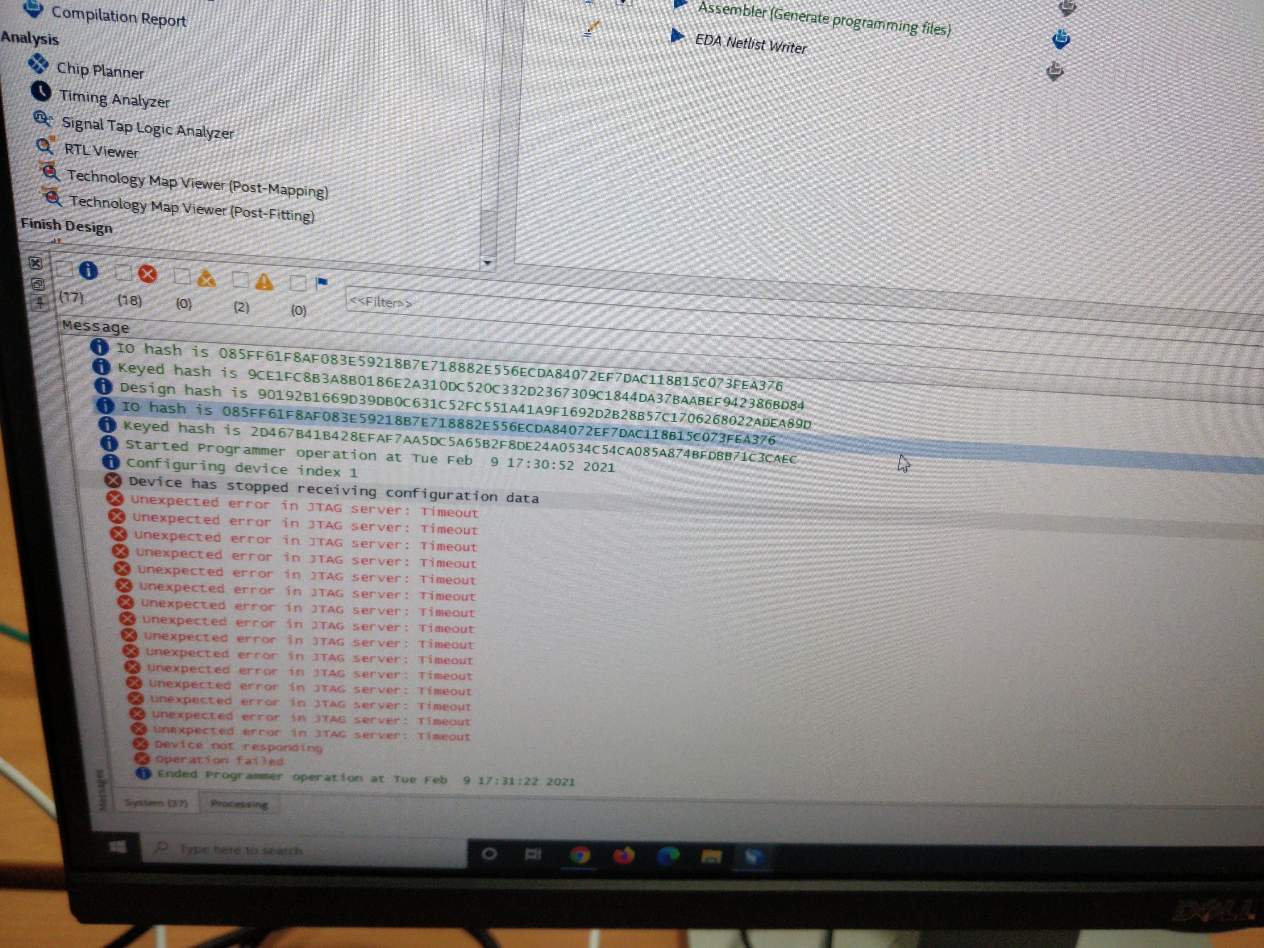
I've got multiple bit stream files I'd like to use for configuration of our agilex FPGA (AGFB014R24A2E3VR0). While the UBII and Power Max 10 chips do seam to work (the board test system shows power and clock stats) the programming (both our bitstream and the intel example bitstreams) always fails at 13% (using both the quartus programmer and the one provided by the BTS). Searching the exact error message (obtained by right click -> copy on the log message) wasn't of any help. We're using Quartus Pro 20.4 on Ubuntu 20 and Windows 10 (neither worked, both with the same issue).
Please review the attached screen shot for further details.
- Mark as New
- Bookmark
- Subscribe
- Mute
- Subscribe to RSS Feed
- Permalink
- Report Inappropriate Content
Hi,
thanks a lot for your help! We've fixed this issue now. One thing we'd like to share, for a potential future reader, is that in addition to the above mentioned article one needs to completely erase the flash prior to configuring. Our working solutions looks like the following:
- Power off the board. Waiting for the caps to be drained doesn't seam to be necessary.
- Set MSEL[2:0] to ON/OFF/OFF
- Power on the board.
- Erase the boards flash using the programmer tools
- Power off the board.
- Set MSEL[2:0] to OFF/OFF/OFF
- Power on the board
- Programm your *.sof file.
It's also required to leave the JTAG chain in the default configuration while erasing the flash. Last but not least: If step 8 fails retry a couple of times until it stops failing (we usually don't need more than 3 tries). It also seams to be more reliable (programming fails less often) at 24MHz than 6MHz, which the programmer defaults to anyway.
Link Copied
- « Previous
-
- 1
- 2
- Next »
- Mark as New
- Bookmark
- Subscribe
- Mute
- Subscribe to RSS Feed
- Permalink
- Report Inappropriate Content
Hi,
thanks a lot for your help! We've fixed this issue now. One thing we'd like to share, for a potential future reader, is that in addition to the above mentioned article one needs to completely erase the flash prior to configuring. Our working solutions looks like the following:
- Power off the board. Waiting for the caps to be drained doesn't seam to be necessary.
- Set MSEL[2:0] to ON/OFF/OFF
- Power on the board.
- Erase the boards flash using the programmer tools
- Power off the board.
- Set MSEL[2:0] to OFF/OFF/OFF
- Power on the board
- Programm your *.sof file.
It's also required to leave the JTAG chain in the default configuration while erasing the flash. Last but not least: If step 8 fails retry a couple of times until it stops failing (we usually don't need more than 3 tries). It also seams to be more reliable (programming fails less often) at 24MHz than 6MHz, which the programmer defaults to anyway.
- Mark as New
- Bookmark
- Subscribe
- Mute
- Subscribe to RSS Feed
- Permalink
- Report Inappropriate Content
Hi,
Recently, I meet the same problem and struggle on it for couple of weeks. I read your solution and wanted to apply it to my PCB. But I encountered one problem when Erase the boards flash. I used the system console -->SDM Debugging Toolkit to erase the flash. However, the Toolkit replied message as shown below:
'QSPI Flash Sector 0x00000000: Erase Error'
It seems that the SDM Debugging Toolkit is useless when the device is not configured.
Can you clarify that how do you erase the boards flash using the programmer tools.
Thank you!
- Mark as New
- Bookmark
- Subscribe
- Mute
- Subscribe to RSS Feed
- Permalink
- Report Inappropriate Content
Well,
We're using the Quartus Programmer to erase the flash. Open the programmer from the Quartus menu -> click on "Auto Detect" to get the correct chain -> select erase for the flash chip -> press start
- Mark as New
- Bookmark
- Subscribe
- Mute
- Subscribe to RSS Feed
- Permalink
- Report Inappropriate Content
Hi,
We've tried your method and the programming always fails at 99%. The error messages are shown below:
'Unexpected error in JTAG server: JTAG chain broken
Unexpected error in JTAG server: JTAG chain broken
Unexpected error in JTAG server: JTAG chain broken
Unexpected error in JTAG server: JTAG chain broken
Device not responding
Unexpected error in JTAG server: JTAG chain broken
Operation failed'
Have you ever met the same problem?
- Mark as New
- Bookmark
- Subscribe
- Mute
- Subscribe to RSS Feed
- Permalink
- Report Inappropriate Content
We indeed sometimes have a problem where the programmer failes at 99 percent but I can't recall ever having received those error messages. Usually the error resolves itself after rebooting the computer running the Jtag server. We redo the above meantioned steps prior to every programming attempt and that seams to work for us.
- Mark as New
- Bookmark
- Subscribe
- Mute
- Subscribe to RSS Feed
- Permalink
- Report Inappropriate Content
Thanks a lot for your replay!
We tried to redo the steps today and it seems sometimes the programmer reached 100% and soon down back to 0%. And another error occurred indicating the failure of FLASH:
'Configuring device index 1
Configuration succeeded at device index 1
Access to flash interface is denied. Potential errors: The device is not configured to setup the flash interface.
Operation failed'
We have checked the FLASH ID selection and the circuits around the FLASH on the PCB and there seems to be no mistakes. Have you ever met the same problem?
- Subscribe to RSS Feed
- Mark Topic as New
- Mark Topic as Read
- Float this Topic for Current User
- Bookmark
- Subscribe
- Printer Friendly Page
- « Previous
-
- 1
- 2
- Next »