- Mark as New
- Bookmark
- Subscribe
- Mute
- Subscribe to RSS Feed
- Permalink
- Report Inappropriate Content
Dear Community,
Intro:
I would like to configure the CVGT on my development kit as a PCIe endpoint.
To do this, I have worked through this guide and synthesised the Avalon-MM reference design ep_g1x4.qsys for the 5CGTFD9EF35C7 on my Dev Kit.
Problem:
The Fitter did some pinning (see, attached pinning file), but I but I doubt that it's the right pinning for my Dev Kit, because the reference design was not explicitly designed for it.
Question:
Do I have to adapt the pinning to my board before programming the CVGT and what is the best way to do this?
Thank you
Best Regards
Link Copied
- Mark as New
- Bookmark
- Subscribe
- Mute
- Subscribe to RSS Feed
- Permalink
- Report Inappropriate Content
Use the Pin Planner from the Assignments menu in Quartus to move pins around.
- Mark as New
- Bookmark
- Subscribe
- Mute
- Subscribe to RSS Feed
- Permalink
- Report Inappropriate Content
Dear sstrell
thank you very much for your answer.
But where can I find a pin description list for the 5CGTFD9EF35? - Google did not help.
The Quartus Pinplanner only shows the pin name and the pin direction. How do I find, for example, on which pins the transceivers are located?
Any idea?
- Mark as New
- Bookmark
- Subscribe
- Mute
- Subscribe to RSS Feed
- Permalink
- Report Inappropriate Content
Use the View menu options, the Pin Finder, and pin tooltips (hover over a pin) to see these right in the tool. The Pin Legend will help.
If you still need it, just search for a device pinout on the Intel web site.
- Mark as New
- Bookmark
- Subscribe
- Mute
- Subscribe to RSS Feed
- Permalink
- Report Inappropriate Content
Ah, I see! Great!
I also found some Pin Description in the "Cyclone V GT FPGA Development Board. Reference Manual.
But there seem to be lots of inputs and outputs in the CV Avalon-MM Interface for PCIe Solutions User Guide's ep_g1x4-entity intended only for simulation.
For instance: PIPE Interface Signals
These PIPE signals are available for Gen1 and Gen2 variants so that you can simulate using either the
serial or the PIPE interface. Simulation is much faster using the PIPE interface because the PIPE
simulation bypasses the SERDES model . By default, the PIPE interface is 8 bits for Gen1 and Gen2. You
can use the PIPE interface for simulation even though your actual design includes a serial interface to the
internal transceivers. However, it is not possible to use the Hard IP PIPE interface in hardware, including
probing these signals using SignalTap® II Embedded Logic Analyzer.(p.30)
Is there a way to tell the Pin Planner that a pin is not used - without removing ist from the vhdl-entity ports list?
- Mark as New
- Bookmark
- Subscribe
- Mute
- Subscribe to RSS Feed
- Permalink
- Report Inappropriate Content
Just don't make an assignment for it in the Pin Planner. If you still want to maintain the signal so it doesn't get optimized away, create Virtual Pin assignments in the Assignment Editor for any top-level pins you want to preserve.
- Mark as New
- Bookmark
- Subscribe
- Mute
- Subscribe to RSS Feed
- Permalink
- Report Inappropriate Content
Dear sstrel,
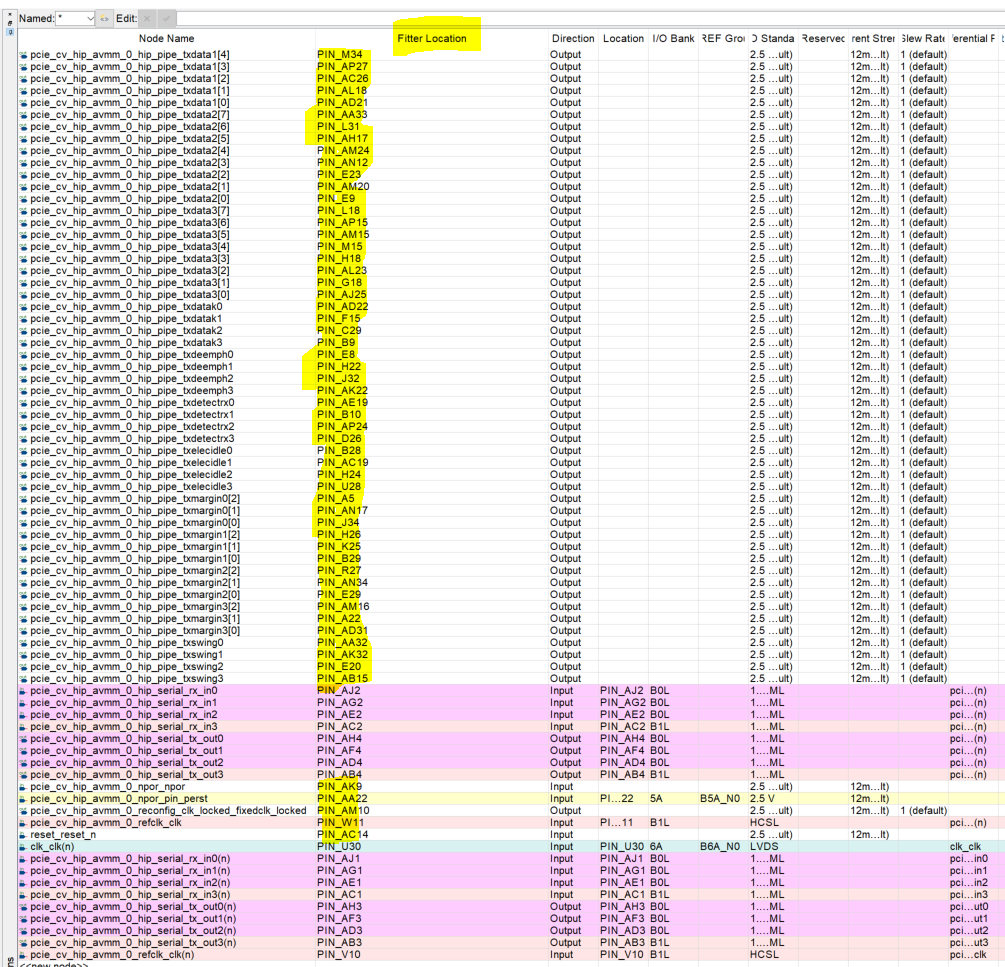
I followed your suggestion, but my fitter just assigns random locations when I leave it blank (see attached picture, yellow marker).
How to prevent?!?
- Mark as New
- Bookmark
- Subscribe
- Mute
- Subscribe to RSS Feed
- Permalink
- Report Inappropriate Content
Useful link: Pin-Outs Files (PDF, TXT, XLS) for all Intel FPGAs:
https://www.intel.com/content/www/us/en/support/programmable/support-resources/devices/lit-dp.html
- Mark as New
- Bookmark
- Subscribe
- Mute
- Subscribe to RSS Feed
- Permalink
- Report Inappropriate Content
As I mentioned, you have to make Virtual Pin assignments to any top-level signals you want to keep but don't want to connect to a physical pin.
- Mark as New
- Bookmark
- Subscribe
- Mute
- Subscribe to RSS Feed
- Permalink
- Report Inappropriate Content
Dear sstrell,
thank you, I now have managed the virtual pins.
- Mark as New
- Bookmark
- Subscribe
- Mute
- Subscribe to RSS Feed
- Permalink
- Report Inappropriate Content
Warning (15104): Quartus Prime software detected a bonding design. Reconfiguration is not supported for Bonded designs and MIF is not created for this design.
What does this mean?
- Mark as New
- Bookmark
- Subscribe
- Mute
- Subscribe to RSS Feed
- Permalink
- Report Inappropriate Content
Dear Community,
I have learned a lot from your help, but I'm left with unresolved issues:
- How can I prevent the Fitter from auto-pinning signals that I have not manually assigned?
- Where can I find the recommended default configuration for unused input and output pins for CVGTFD9E5F35C7?
-
And there are still three nodes whose signals are not PIPE simulation only nodes and and yet their pinning is not described in the cv-avmm-manual:
- pcie_cv_hip_avmm_0_npor_npor (input),
- dut_reconfig_busy_reconfig_busy (input),
- pcie_cv_hip_avmm_0_reconfig_clk_locked_fixedclk_locked (output)
I would be very happy if someone had an idea about this.
- Mark as New
- Bookmark
- Subscribe
- Mute
- Subscribe to RSS Feed
- Permalink
- Report Inappropriate Content
Got a little further:
1. Avalon MM Reference Design is a Qsys Design, so I could remove Pin-Out-signals
a) by removing it from the Export column or
b) by generating a Top-Level-Unit from within the Pin Planner for the qip-file, then instantiate the qip file in the Top-Level-Unit and comment out unwanted Out-Pins.
c) Also I found a possibility to delete Pins in the Pin Planner using the context menu of the pin.
2. For default pin configuration I found:
set_global_assignment -name RESERVE_ALL_UNUSED_PINS "AS INPUT TRI-STATED"
set_global_assignment -name RESERVE_ALL_UNUSED_PINS_NO_OUTPUT_GND "AS INPUT TRI-STATED"
in the corresponding Golden Reference Design qsf file.
Hope this is correct and sufficient not to damage the board.
3. For pcie_cv_hip_avmm_0_npor_npor I generated a signal by ORing perst and nreset as described here:
npor <= pcie_cv_hip_avmm_0_npor_pin_perst or reset_reset_n;
and assigning it to the port in the Top-Level-Unit-Instantiation. Hope that is correct.
For: dut_reconfig_busy_reconfig_busy (input), pcie_cv_hip_avmm_0_reconfig_clk_locked_fixedclk_locked, still no idea.
I have commented it out in the Top-Level-Unit for now.
- Mark as New
- Bookmark
- Subscribe
- Mute
- Subscribe to RSS Feed
- Permalink
- Report Inappropriate Content
As I understand it, the warning is to remind customer that a bonded XCVR design is used. Due to dynamic reconfiguration is not support for bonded XCVR, the MIF file which was required for reconfiguration is not generated.
If you do not use dynamic reconfiguration, this warning can be safely ignored. Else, if you are planning to perform reconfiguration to the XCVR, you should take noted of the unsupported reconfiguration for bonded XCVR. Can refer to the "Unsupported Reconfiguration Modes" in the Cyclone V Device Handbook, Volume 2: Transceivers for further details.
- Mark as New
- Bookmark
- Subscribe
- Mute
- Subscribe to RSS Feed
- Permalink
- Report Inappropriate Content
Dear AR_A_Intel,
O.K. I see. So probably I can ignore this for now, until I know what dynamic transceiver reconfituration is needed for.
Thank you very much!
- Mark as New
- Bookmark
- Subscribe
- Mute
- Subscribe to RSS Feed
- Permalink
- Report Inappropriate Content
Hope everything is working well at your side. I will now transition this thread to community support. If you have a new question, feel free to open a new thread to get the support from Intel experts. Otherwise, the community users will continue to help you on this thread. Thank you.
- Subscribe to RSS Feed
- Mark Topic as New
- Mark Topic as Read
- Float this Topic for Current User
- Bookmark
- Subscribe
- Printer Friendly Page