- Mark as New
- Bookmark
- Subscribe
- Mute
- Subscribe to RSS Feed
- Permalink
- Report Inappropriate Content
Hello,
I need to control my camera OV7670 with I2C protocol (so it's best to use nios II i think) and i need to interface it with VGA and some image processing VHDL files, which will be fetching image from SDRAM (32 MB ISSI sdram) after it will be loaded there from camera (1. load image to sdram from camera though VHDL code, 2. process image to another place in SDRAM memory, 3. output processed file to VGA and mayby PC). Is it possible to somehow connect VHDL files (.vhd) with Qsys? Is this the best way for my project or should i choose another approach? I am asking You, because i dont want to do redundant work that will lead me to nowhere mayby...Link Copied
- Mark as New
- Bookmark
- Subscribe
- Mute
- Subscribe to RSS Feed
- Permalink
- Report Inappropriate Content
- Mark as New
- Bookmark
- Subscribe
- Mute
- Subscribe to RSS Feed
- Permalink
- Report Inappropriate Content
- Mark as New
- Bookmark
- Subscribe
- Mute
- Subscribe to RSS Feed
- Permalink
- Report Inappropriate Content
I am working currently on interfacing SDRAM using Qsys component (without nios) and i think that i will use some microprocessor (STM32l100rct6 probably) for I2C setup for my camera, because there is no I2C component for Qsys and ive found I2C controller on opencores but i think using uC will make it a bit easier - will report if ill manage to get some satisfying results.
- Mark as New
- Bookmark
- Subscribe
- Mute
- Subscribe to RSS Feed
- Permalink
- Report Inappropriate Content
- Mark as New
- Bookmark
- Subscribe
- Mute
- Subscribe to RSS Feed
- Permalink
- Report Inappropriate Content
... it works without QSYS.
When you manage to get it to work - this way or another - I'm looking for somebody to team up with to demistify the register set for the standard Hamsterworks project, i.e. to get a proper image on the connected VGA monitor.- Mark as New
- Bookmark
- Subscribe
- Mute
- Subscribe to RSS Feed
- Permalink
- Report Inappropriate Content
With a DE0-Nano Board (http://www.terasic.com.tw/cgi-bin/page/archive.pl?language=english&no=593) your FPGA has enough memory to store a 160x120 image, as used in the Hamsterworks code.
- Mark as New
- Bookmark
- Subscribe
- Mute
- Subscribe to RSS Feed
- Permalink
- Report Inappropriate Content
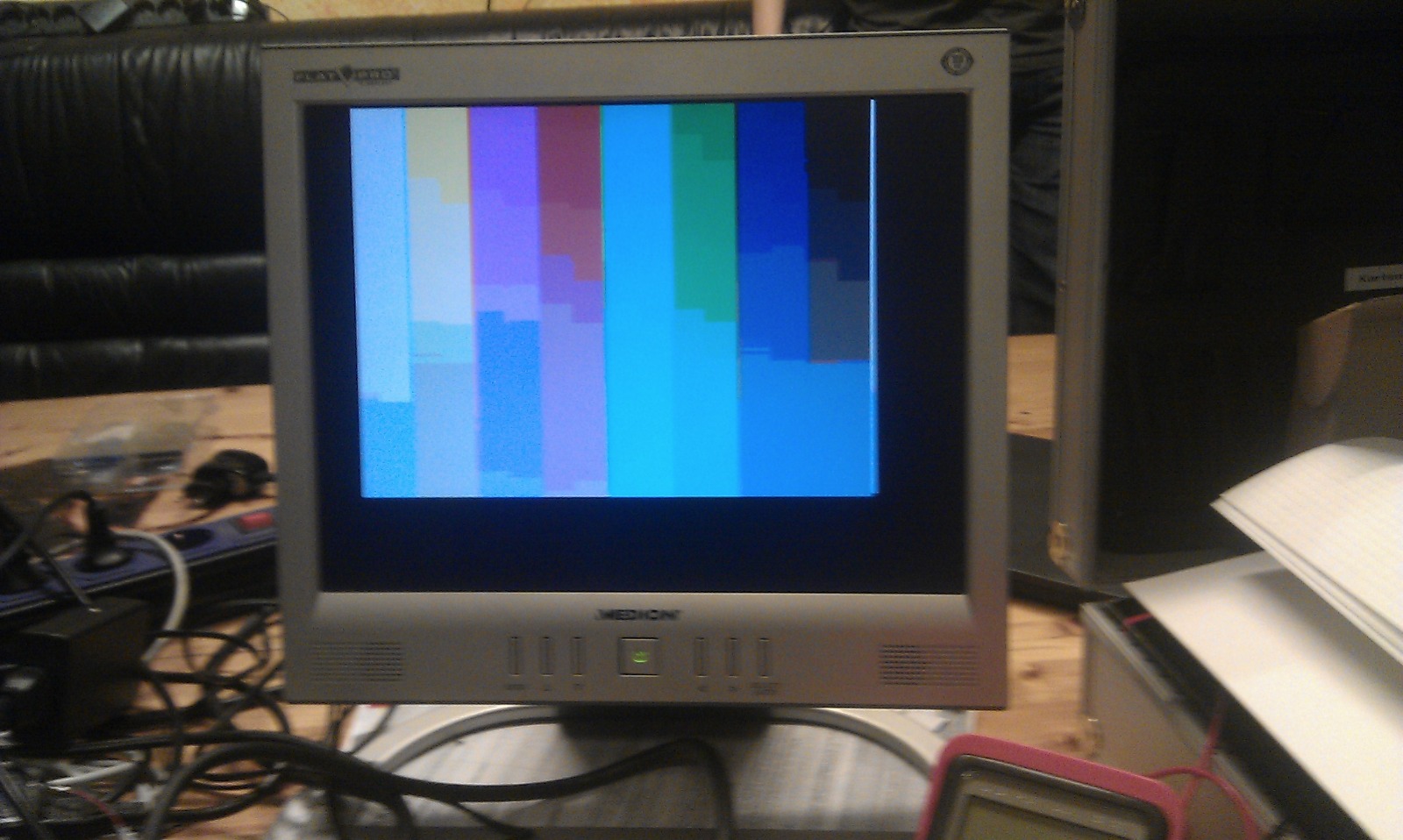
I have already achieved 160x120 image, but whole image is quite "yellow" (i will place video here but tomorrow, when ill get better light from sun rather than bulb). Also i had to change some registers, IMO Hamster made few mistakes:
- check register 0x3E with value 0x19 - PCLK scaling comment says that PCLK = 4, its not true, PCLK is 2 with this setup (check datasheet); - register 0x73 is set to value 0xF1 - ive changed it to 0x01 (4 oldest bits are reserved and initially set to 0) - he set lowest set bit correctly for PCLK = 2; - register 0xA2 is set to value 0x02 - ive changed it to 0x01 (0x02 stands for PCLK divided by 4 - checked with oscilloscope); - also commented all other registers setup from 0xA2 (when x"14"-...-x"36") - better quality in my opinion Two funny things: - cant find information about register 0xA2 in datasheet (9F-AB Histogram-based AEC/AGC ControlXX–Histogram-based AEC/AGC Control); - Hamster I2C reset command seems not working - i mean when i reprogram fpga when it has already some VHDL description in it camera bahaves different than if i upload VHDL design after powering up the de0 nano device - this may be cause of all of my problems (with colors in example and the image quality is quite bad), thats why i wanted to use uC for I2C setup. As i've said, ill upload video of my results tomoroww and also i can upload project if You want, but ill be working on interfacing design with SDRAM to get better resolution and quality anyway . 1 more thing - im using 5 bit DAC for each color, so im setting 3 oldest R, 3 oldest G and 2 oldest B (same 8bit setup from hamsterworks) - rest of bits are set to "0":vga_red <= frame_pixel(7 downto 5) & "00";
vga_green <= frame_pixel(4 downto 2) & "00";
vga_blue <= frame_pixel(1 downto 0) & "000"; edit and here's video showing results of above operations [video=youtube;F1W-AwpiE1M]https://www.youtube.com/watch?v=F1W-AwpiE1M[/video] About visible colorful noise - i think its wire's fault, it behaves better when i hold cables connecting ov7670 (PCLK = 12,5 MHz) or when i use lower PCLK (PCLK = 4 -> PCLK = 6,25 MHz) - in the other situation i receive like 4 frames divided on LCD showing same scenario with some shift - im thinking about changing some clocks in design mayby it will help, anyway my goal now as i mentioned many times is to get better resolution by adding SDRAM (also better colors). Im suprised that quality of shown video is bad if it is about colors, i mean RGB 3-3-2 gives about 2^3*2^3*2^2 = 256 color combinations and presented images are very monochrome (depending of light).
- Mark as New
- Bookmark
- Subscribe
- Mute
- Subscribe to RSS Feed
- Permalink
- Report Inappropriate Content
It works now.
I was having problems with focus, one had to turn the focus wheel on the camera. And it has to be horizontally and vertically mirrored. Yes! Thank you very much !!!- Mark as New
- Bookmark
- Subscribe
- Mute
- Subscribe to RSS Feed
- Permalink
- Report Inappropriate Content
You can share video/photo of result that you achieved, I would like to compare quality with mine project.
- Subscribe to RSS Feed
- Mark Topic as New
- Mark Topic as Read
- Float this Topic for Current User
- Bookmark
- Subscribe
- Printer Friendly Page