- Mark as New
- Bookmark
- Subscribe
- Mute
- Subscribe to RSS Feed
- Permalink
- Report Inappropriate Content
Hello,
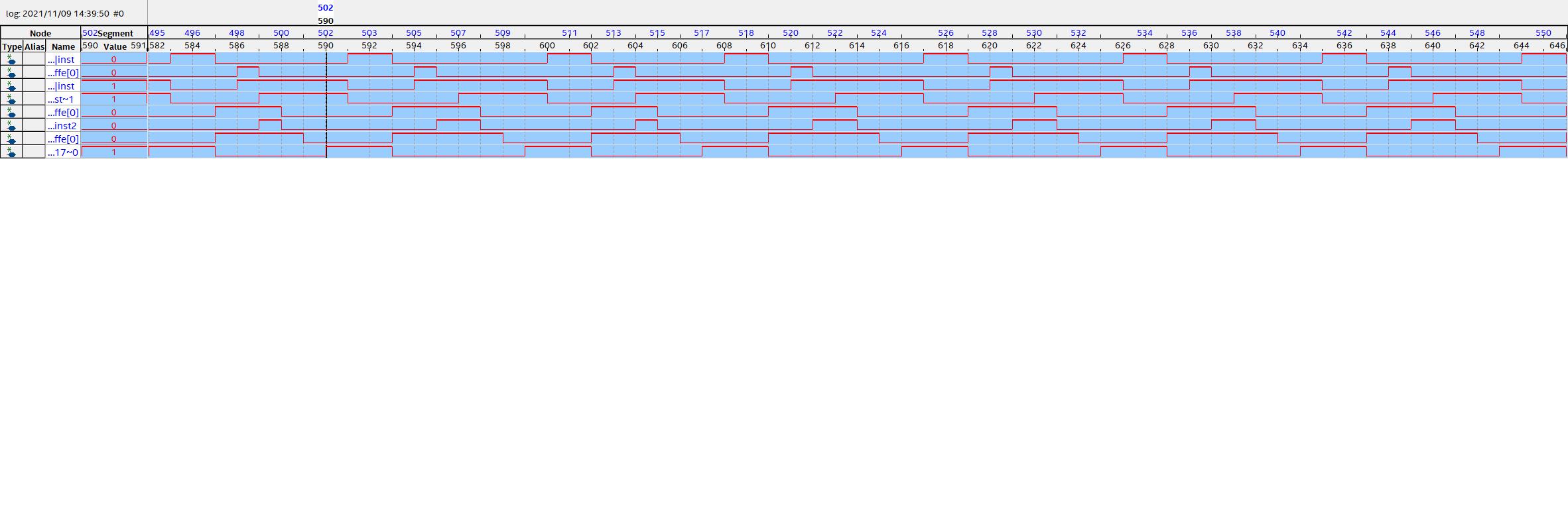
I am using the SignalTap II logic analyzer on Quartus Prime Version : 18.1.1 Build 646 04/11/2019 SJ Standard Edition. I am tracing logic in the Cyclone V SOC. The logic under analysis uses a 100MHz clock produced by an instance of sys_clks_pll. This instance also produces a 200MHz clock. I am using the 200MHz clock for the trace to make sure the LA detects the edges. I provide you with a JPEG of the trace I captured. I need to figure out the time scale of the display. I infer that the time base intervals should be 5ns. I also need to know if it is OK to use a 200MHz clock since the user's guide states I should use the same frequency as the logic being traced.
Thanks for your help.
Ben
- Mark as New
- Bookmark
- Subscribe
- Mute
- Subscribe to RSS Feed
- Permalink
- Report Inappropriate Content
Any clock in the design can be used as the sampling clock. Typically, you'll use the clock for the logic you are looking at, but there is nothing stopping you from using a faster clock to get better sampling resolution. If you're sampling clock is 200 MHz, then yes, each sample is 5 ns.
Link Copied
- Mark as New
- Bookmark
- Subscribe
- Mute
- Subscribe to RSS Feed
- Permalink
- Report Inappropriate Content
Any clock in the design can be used as the sampling clock. Typically, you'll use the clock for the logic you are looking at, but there is nothing stopping you from using a faster clock to get better sampling resolution. If you're sampling clock is 200 MHz, then yes, each sample is 5 ns.
- Subscribe to RSS Feed
- Mark Topic as New
- Mark Topic as Read
- Float this Topic for Current User
- Bookmark
- Subscribe
- Printer Friendly Page