- Mark as New
- Bookmark
- Subscribe
- Mute
- Subscribe to RSS Feed
- Permalink
- Report Inappropriate Content
Link Copied
- Mark as New
- Bookmark
- Subscribe
- Mute
- Subscribe to RSS Feed
- Permalink
- Report Inappropriate Content
Hello Brandom,
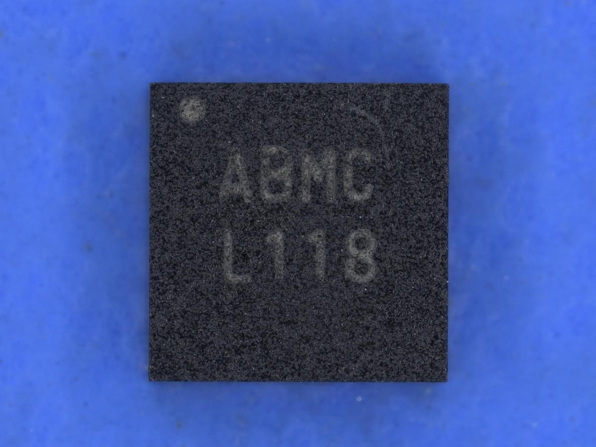
In our Power regulators datasheet, Enpirion only shows the packaging top marking.
The package top marking that you attached is correct, and also the die ref number is correct but this is only for internal ref.
What you are marking in red squares is the internal inductor winding start and end points.
Regards,
Mostafa
- Mark as New
- Bookmark
- Subscribe
- Mute
- Subscribe to RSS Feed
- Permalink
- Report Inappropriate Content
Mostafa,
Ok, so is it normal for the "internal inductor winding start and end points" to be at different locations?
I'm seeing this differ from part to part.
The internal die marking "IC1012" can't be validated, correct?
Let me know by day end today. I need to close out my case, thanks!!
- Mark as New
- Bookmark
- Subscribe
- Mute
- Subscribe to RSS Feed
- Permalink
- Report Inappropriate Content
Hello Brandom,
The internal inductor looks like a bead and the die is stacked over it and inside the inductor package it is expected that the start and end points will rotated based on the inductor orientation.
So during the device assembly there are 4 expected positions for that Inductor to be mounted depending on its orientation and we don't control that orientation, only we mount the bead from its metal terminal.
So it is expected that when you do the x-ray to have 1 of 4 expected different images for the inductor winding from device to the other.
Regarding the die marking; it is the same for all EP5388QI devices.
Regards,
Mostafa
- Subscribe to RSS Feed
- Mark Topic as New
- Mark Topic as Read
- Float this Topic for Current User
- Bookmark
- Subscribe
- Printer Friendly Page