Designing with AXI Workshop Lab - Verifying Your Project
Success! Subscription added.
Success! Subscription removed.
Sorry, you must verify to complete this action. Please click the verification link in your email. You may re-send via your profile.
- Intel Community
- Intel Community Knowledge Base
- Product Support Forums Knowledge Base
- FPGA Knowledge Base
- FPGA Wiki
- Designing with AXI Workshop Lab - Verifying Your Project
Designing with AXI Workshop Lab - Verifying Your Project
- Subscribe to RSS Feed
- Mark as New
- Mark as Read
- Bookmark
- Subscribe
- Printer Friendly Page
- Report Inappropriate Content
Designing with AXI for Altera SoC ARM Devices Workshop Lab - Verifying Your Project
Overview
In this section, you will download your compiled design to your SoCKit board, boot Linux, and run the verification application.
<<<<Click here to return to the previous section
Downloading Your Programming File and Booting Linux
For this section, you will need a terminal program capable of communicating with the on-board serial port via a USB connection to the board.
1. Configure your terminal program with the following settings:
115200 baud, 8 bits, one stop bit, no parity, no flow control.
You will need a terminal program capable of communicating to an FTDI serial device via USB. Altera recommends PuTTY for this lab.
If you need help configuring PuTTY, please refer to this link for help: Setting Up PuTTY
If you prefer to use minicom, please refer to this link for help: Setting Up Minicom
2. Insert the microSD card you were given in class into the microSD card slot on the bottom of the SoCKit board.
d/d8/Axilab-sockit-sdc.JPG ( Axilab-sockit-sdc.JPG - click here to view image )
3. Power-on your board, then open the serial terminal program on your PC.
4. There are two versions of the microSD card. If you received your microSD card in June of 2014, please proceed to the next step (5.)
If you received your microSD card after June of 2014, please proceed to step 6.
5. The SoCKit board will boot from the microSD card. Once the preloader has completed, it will start u-boot.
u-boot has a 5 second delay before it launches Linux. You must hit the "Enter" key in the terminal program
before u-boot completes its 5 second countdown.
If Linux begins to boot before you are able to interrupt u-boot, you will need to power-cycle your board and restart the terminal program.
6. In the terminal program, hit the "Enter" key to get a u-boot prompt.
7. In the Quartus GUI, from the "File" menu, select "Open...".
8. In the "Open File" dialog box, change the "Files of type:" to "Programming Files" and open the file "soc_system.cdf".
Be sure you are in the "SoCKitAXILab" project directory.
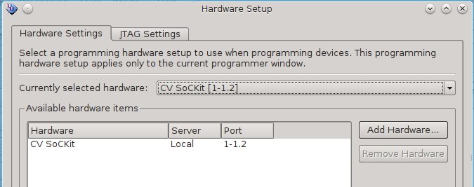
9. Click the "Hardware Setup..." button to open the "Hardware Setup" dialog box.
10. Select the USB Blaster integrated into the SoCKit board, then click "Close".
e/ef/Axilabprog1.jpeg ( Axilabprog1.jpeg - click here to view image )
11. In either the JTAG chain schematic or list view, select the "5CSXFC6D6F31xx" device.
12. Click the "Change File..." button, browse to the "output_files" directory, select "soc_system.sof", and click "Open".
13. Check the "Program/Configure" box in the file list.
6/6c/Axilabprog2.jpeg ( Axilabprog2.jpeg - click here to view image )
14. Click "Start" to program the FPGA portion of the Cyclone V SoC device.
15. Once the FPGA is configured, in your terminal program, type "boot" to boot Linux.
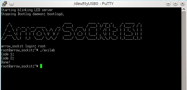
16. Once Linux has booted, login as "root", no password is required.
17. At the Linux prompt, type:
./axilab
then hit "Enter".
18. Note down the two codes printed out by the application.
These codes will be entered into the survey below to verify that you have successfully completed the lab and allow you to
select your thank-you gift.
e/e2/Axilablinux.jpeg ( Axilablinux.jpeg - click here to view image )
19. Congratulations! You have now completed the Designing with AXI for Altera SoC ARM Devices Workshop Lab.
Please go to the link below to complete a short feedback survey, enter your completion codes, and select your thank-you gift!
Community support is provided during standard business hours (Monday to Friday 7AM - 5PM PST). Other contact methods are available here.
Intel does not verify all solutions, including but not limited to any file transfers that may appear in this community. Accordingly, Intel disclaims all express and implied warranties, including without limitation, the implied warranties of merchantability, fitness for a particular purpose, and non-infringement, as well as any warranty arising from course of performance, course of dealing, or usage in trade.
For more complete information about compiler optimizations, see our Optimization Notice.