Designing with AXI for Altera SoC ARM
Success! Subscription added.
Success! Subscription removed.
Sorry, you must verify to complete this action. Please click the verification link in your email. You may re-send via your profile.
- Intel Community
- Intel Community Knowledge Base
- Product Support Forums Knowledge Base
- FPGA Knowledge Base
- FPGA Wiki
- Designing with AXI for Altera SoC ARM
Designing with AXI for Altera SoC ARM
- Subscribe to RSS Feed
- Mark as New
- Mark as Read
- Bookmark
- Subscribe
- Printer Friendly Page
- Report Inappropriate Content
Designing with AXI for Altera SoC ARM Devices Workshop Lab - Creating Your AXI3 Component
(Redirected from Designing with AXI for Altera SoC ARM Devices Workshop Lab - Instructions)
Overview
In this section you will unzip the lab files and create your own AXI3 QSys Component.
<<<<Click here to return to the previous section
Accessing the Project Files
1. Unzip the project files into a working directory on your computer
2. Under the target directory, go to the "ip\axi3_slave_example" directory and open the file "axi3_slave_example.sv"
Note that the file has all the signals required for an AXI3 slave interface in the format "axs_<AXI Signal Name>".
This allows the component editor to read in the file and auto-populate the functionality of most of these signals.
Also note that the file has 3 parameters to specify the width of the configurable AXI signals.
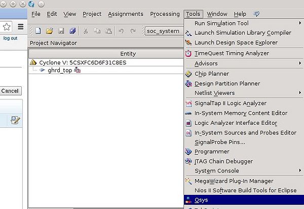
3. Start Quartus II version 13.1.4 and open the project "soc_system.qpf"
4. Launch QSys by selecting the "Tools" menu in Quartus then selecting "QSys"
e/e1/Axilabqsys.jpeg ( Axilabqsys.jpeg - click here to view image )
5. Click "Close" in the "Initializating Completed" dialog box
6. In the "Open" dialog box, select "soc_system.qsys" and hit "Open"
Review the SoC HPS AXI Bridges Configuration
Scroll to the top of the "System Contents" view, right-click on the instance of "hps_0"
This is the SoC ARM Hard Processor Subsystem
Note the width of the AXI Bridges. The HPS-to-FPGA interface width should be 64-bit
9/91/Axilabhpsedit.jpeg ( Axilabhpsedit.jpeg - click here to view image )
Hit "Cancel" to close the hps_0 GUI
Create a Custom QSys Component for an Existing AXI Slave Example
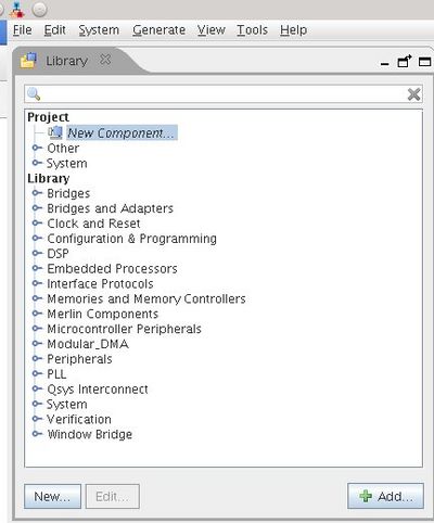
1. In the "Library" tab, either double-click New Component... or click the "New..." button to open the "Component Editor" GUI
8/80/Axilabnewcomp.jpeg ( Axilabnewcomp.jpeg - click here to view image )
2. In the "Component Type" tab,
enter "axi3_slave_example" in the "Name:" field, this will be the base of the file name for the component TCL description file.
enter "AXI3 Slave Example" in the "Display Name:" field, this will be the name displayed in the Component Library.
b/b0/Axilabce.jpeg ( Axilabce.jpeg - click here to view image )
3. Click on the "Files" tab of the Component Editor
4. Under Synthesis Files, click the "+" button and browse to the "ip\axi3_slave_example" directory under the project directory.
Select the "axi3_slave_example.sv" and "lab_checker.sv" files and click "Open".
5. Ensure that "Top-level File" is in the "Attributes" column for the file "axi3_slave_example.sv".
6. Click the "Analyze Synthesis Files" button to read in the example design files.
7. Click "Close" on the "Analyze Synthesis Files" dialog box.
You will see an error in the Component Editor messages panel which we will address shortly.
d/d9/Axilabce1.jpeg ( Axilabce1.jpeg - click here to view image )
8. Click the "Interfaces" tab in the Component Editor.
9. Click on the grey triangle next to the ""clock" (Clock Input)" and ""reset" (Reset Input)" interfaces to minimize them
10. Click the "Add Interface"" button to this will default to an Avalon Memory Mapped Slave
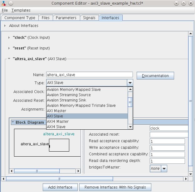
11. Click the "Type:" drop down menu and select "AXI Slave"
Note: Be sure to select "AXI Slave", not "AXI4 Slave"
"AXI Slave" specifies an AXI3 slave and this component is an AXI3 slave.
d/da/Axilabce3.jpeg ( Axilabce3.jpeg - click here to view image )
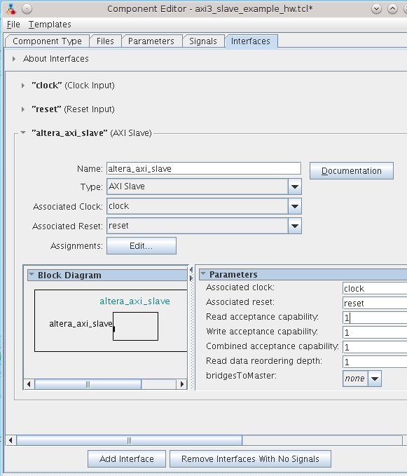
12. Click the "Associated Reset:" drop down menu and select "reset".
13. Ensure the read, write, and combined acceptance capability is set to 1.
This example slave cannot accept outstanding transactions.
14. Ensure that Read data reordering depth is set to 1.
This example slave will not reorder read data.
b/b7/Axilabce4.jpeg ( Axilabce4.jpeg - click here to view image )
15. Click on the "Parameters" tab
Note that the Component Editor has auto-populated the 3 parameters defined in the top-level file "axi3_slave_example.sv".
Also note that it has not auto-populated the "localparam" defined in in this file.
16. Click on the "Signals" tab in the Component Editor
Note that the Component Editor has auto-populated all the IO signals in "axi3_slave_example.sv" and assigned most of them
their correct "Signal Type."
Also note that the Component editor has correctly auto-populated the component parameters including calculating the WSTRB width.
We will need to assign each signal to the AXI3 interface we created in steps 10-14.
17. Next to the "axs_awid" signal, click in the blank "Interface" box to pop-up the drop down menu and select "altera_axi_slave".
Note: if you inadvertently select an italicized new interface in this menu, you will need to return to the "Interfaces" tab
before finishing the component and click "Remove Interfaces with No Signals".
18. Repeat this step for all of the AXI3 signals.
19. You will find that the "Signal Type" for 5 of the signals was not auto-populated correctly,
click on the incorrect signal type and select the correct signal type from the drop down menu.
Ensure all signal types match the signal name correctly.
a/a1/Axilabce5.jpeg ( Axilabce5.jpeg - click here to view image )
20: Click "Finish..." then "Yes, Save".
Note that your "AXI3 Slave Example" component now appears in the "Library" tab in QSys just under "New Component..."
Community support is provided during standard business hours (Monday to Friday 7AM - 5PM PST). Other contact methods are available here.
Intel does not verify all solutions, including but not limited to any file transfers that may appear in this community. Accordingly, Intel disclaims all express and implied warranties, including without limitation, the implied warranties of merchantability, fitness for a particular purpose, and non-infringement, as well as any warranty arising from course of performance, course of dealing, or usage in trade.
For more complete information about compiler optimizations, see our Optimization Notice.