- Mark as New
- Bookmark
- Subscribe
- Mute
- Subscribe to RSS Feed
- Permalink
- Report Inappropriate Content
Hi,
I am using EP53A8LQI in my design. I have designed it for Vout of 1.2V using Resistor divider network. But im not getting the desired output voltage of 1.2V also there is a noise coming from VFB pin. I the pin is pressed the noise disappears.
Attached is the schematics for reference. Please suggest me a solution
- Mark as New
- Bookmark
- Subscribe
- Mute
- Subscribe to RSS Feed
- Permalink
- Report Inappropriate Content
Hi Shifali,
Based on your measurement, it looks there is an instability issue.
Could you please insert 22pF on top of R118 (Ra) to check if that helps to stabilize the system.
I have approved the FA request, i will send a personal email with the details on how to ship the failed units to Intel FA lab.
Also i have noticed that you already opened an IPS case for this issue, so i will copy the same details there too.
Thanks,
Mostafa
Link Copied
- Mark as New
- Bookmark
- Subscribe
- Mute
- Subscribe to RSS Feed
- Permalink
- Report Inappropriate Content
Hi Shifali
Thanks for your inquiry. May I know is this happened to other boards as well? Have you checked the soldering quality when you mentioning that pressing on the pin will eliminate the noise? What is the output voltage when the pin is/isn't pressed?
Thanks.
Eng Wei
- Mark as New
- Bookmark
- Subscribe
- Mute
- Subscribe to RSS Feed
- Permalink
- Report Inappropriate Content
Hello,
We have assembled both the boards and we are finding the same issue.
The measured output voltage is 0.5V where the designed voltage is for 1.2V. Is it mandatory to generate the voltage using VS0,VS1 and VS2.
Also when the circuit is mounted in general purpose PCB its generating a voltage of 2.8V
- Mark as New
- Bookmark
- Subscribe
- Mute
- Subscribe to RSS Feed
- Permalink
- Report Inappropriate Content
- Mark as New
- Bookmark
- Subscribe
- Mute
- Subscribe to RSS Feed
- Permalink
- Report Inappropriate Content
Hello Shifali,
I have reviewed your schematic and looks ok.
Could you please help to confirm the part to mark is AJXX not AMXX.
Please help to probe Vout and Vin signals and share scope waveform for the startup.
It seems that the OCP triggered during the startup and this is why you measure 0.5V.
Please also help to share a screenshot for the layout for review.
Thanks,
Mostafa
- Mark as New
- Bookmark
- Subscribe
- Mute
- Subscribe to RSS Feed
- Permalink
- Report Inappropriate Content
Hi,
The top marking is checked and its AJ.
Please find the attached snapshot of layout.
Also find the attached snapshot of VIN and VOUT. We are not getting any output voltage once we replaced the IC.
- Mark as New
- Bookmark
- Subscribe
- Mute
- Subscribe to RSS Feed
- Permalink
- Report Inappropriate Content
Hi Mostafa,
The Sample IC was rigged up in general purpose PCB and below are the observations.
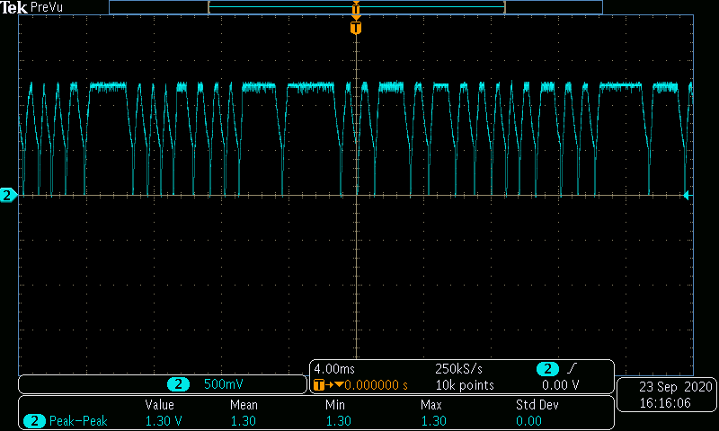
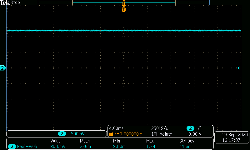
The IC is functioning properly only for supply voltage of 3.3V for both VID selection settings and resistor feedback settings. When 5V is applied the constant output is not obtained for both the VID selection settings and resistor feedback settings. Below are the wave forms attached for different test conditions.
Fig A: VID selection settings. Vin=3.3V and Vout=1.2V
Fig B: VID selection settings. Vin=5V and Vout=Fluctuating
Fig C: Resistor feedback settings. Vin=3.3V and Vout=1.2V
Fig
- Mark as New
- Bookmark
- Subscribe
- Mute
- Subscribe to RSS Feed
- Permalink
- Report Inappropriate Content
Hi Shifali,
Thanks a lot for your analysis.
Before i approve the failure analysis for this issue, it looks like you could have a hot plug or high ramping rate for the 5Vin.
So you you please probe VIN and Vout signal and shows only the startup event when the 5V starting up.
Also please test again with replacing R104 with 10Ohm and C105 with 10uF.
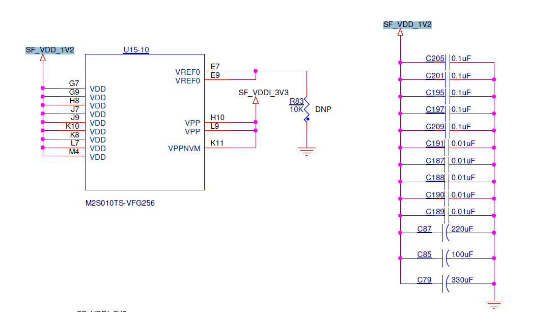
Also please let me know what is the total output capacitance attached to SF_VDD_1V2 where if the capacitance higher than 150uF this could cause a high inrush current that will trigger the OCP.
So if you have any high capacitance attached there, please try to reduce the total capacitance to 100uF and test again.
Also what is the load type that connected to the output of EP53A8?
Thanks,
Mostafa
- Mark as New
- Bookmark
- Subscribe
- Mute
- Subscribe to RSS Feed
- Permalink
- Report Inappropriate Content
Hi Mostafa,
The EP53A8 load is Microsemi FPGA which requires current of 500mA. The output of EP53A8 regulator is directly connected Microsemi FPGA core voltage. Hence even the FPGA decoupling capacitors add on to SF_VDD_1V2 .
Attached is the image of decoupling capacitor used for Microsemi FPGA.
- Mark as New
- Bookmark
- Subscribe
- Mute
- Subscribe to RSS Feed
- Permalink
- Report Inappropriate Content
Hi Shifali,
Thanks a lot for sharing the decoupling capacitance, it seems you have more than 150uF on the FPGA side.
So for test purpose could you please remove the 330uF and 220uF from the loop and check if the issue still exist or already solved.
From my experience: based on the FPGA loading current step <500mA and the EP53A8 ripple and transient performance, i don't think you will need 650uF as decoupling capacitance.
You can replace that capacitance with high frequency caps <10uF which will help to reduce the high frequency noise from the 1.2V rail.
Thanks,
Mostafa
- Mark as New
- Bookmark
- Subscribe
- Mute
- Subscribe to RSS Feed
- Permalink
- Report Inappropriate Content
Hi Mostafa,
Thanks a lot for your support so far.
I have replaced the load tantalum capacitors with 2x1uF capacitors and one with 22uF capacitors. And I am not finding the voltage drop issue.
But this is tested with Vin=3.3V and not 5V.
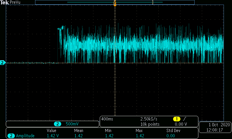
Also find the attached waveform of VIN and Vout signal that shows the startup event when the 5V starting up.
Fig A: Input waveform. Vin =5V
Fig B: Output waveform
- Mark as New
- Bookmark
- Subscribe
- Mute
- Subscribe to RSS Feed
- Permalink
- Report Inappropriate Content
- Mark as New
- Bookmark
- Subscribe
- Mute
- Subscribe to RSS Feed
- Permalink
- Report Inappropriate Content
- Mark as New
- Bookmark
- Subscribe
- Mute
- Subscribe to RSS Feed
- Permalink
- Report Inappropriate Content
Hi Shifali,
I am sorry, I was off since last Friday.
Based on your measurement analysis the issue fixed when you reduce the output caps at Vin=3.3V.
But the issue still exist at 5Vin.
Unfortunately your shared measurement doesn't give me enough information.
So if you could just zoom out for two of the voltage drop cycles so i can check if that OCP or something else.
I approve the FA for your case, so please help to fill the DPR form (will send you a personal email with the DPR form) which is needed to process the FA request.
Thanks,
Mostafa
- Mark as New
- Bookmark
- Subscribe
- Mute
- Subscribe to RSS Feed
- Permalink
- Report Inappropriate Content
Hi Mostafa,
I have attached the zoomed out waveforms of Vin and Vout. Hope this is helpful.
Also could you please let me know the significance of FA request form.
- Mark as New
- Bookmark
- Subscribe
- Mute
- Subscribe to RSS Feed
- Permalink
- Report Inappropriate Content
Hi Shifali,
Thanks a lot for taking the measurement again, but i am sorry for my typo in my previous response, i would like to see only two cycles from the voltage noise issue to check if the system goes to a soft start or it is stability issue.
Regarding The FA (failure analysis): it will be performed by Intel application Engineer who will test Ep53A8L for production test and check if there is any functional issue with the device or not.
Based on your analysis: the voltage noise occurs with Vin>3.3v and under that condition Intel engineer will test the device.
So for the FA process, i need to submit the request on the system for issue tracking and then you can ship up to 5 samples that shows that faulty behavior for FA.
Please let me knw if you would like to proceed with the FA.
Thanks,
Mostafa
- Mark as New
- Bookmark
- Subscribe
- Mute
- Subscribe to RSS Feed
- Permalink
- Report Inappropriate Content
Hi Mostafa,
I would like to proceed with FA.
- Mark as New
- Bookmark
- Subscribe
- Mute
- Subscribe to RSS Feed
- Permalink
- Report Inappropriate Content
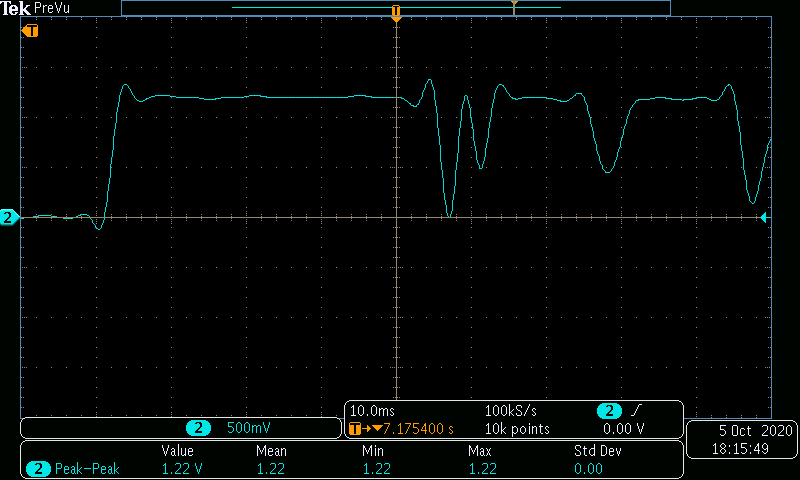
Hi Mostafa,
Also find the attached waveform. Hope I have shared correct expected waveform of Vout.
- Mark as New
- Bookmark
- Subscribe
- Mute
- Subscribe to RSS Feed
- Permalink
- Report Inappropriate Content
Hi Shifali,
Based on your measurement, it looks there is an instability issue.
Could you please insert 22pF on top of R118 (Ra) to check if that helps to stabilize the system.
I have approved the FA request, i will send a personal email with the details on how to ship the failed units to Intel FA lab.
Also i have noticed that you already opened an IPS case for this issue, so i will copy the same details there too.
Thanks,
Mostafa
- Mark as New
- Bookmark
- Subscribe
- Mute
- Subscribe to RSS Feed
- Permalink
- Report Inappropriate Content
Hi Mostafa,
Is it possible for you to test with the ICs that you have since we are observing that issue in all the sample ICs.
- Mark as New
- Bookmark
- Subscribe
- Mute
- Subscribe to RSS Feed
- Permalink
- Report Inappropriate Content
Hi Shifali,
Since the issue exists on all samples you have, that's mean you have a design issue.
I didn't see that issue with my test board and it works fine.
I thought you have only one or two samples that have that stability issue.
I would like to have a call with you, so we can review the design together.
I will send a skype call invitation to your email, please help to reschedule if the time is not suitable.
Thanks,
Mostafa
- Subscribe to RSS Feed
- Mark Topic as New
- Mark Topic as Read
- Float this Topic for Current User
- Bookmark
- Subscribe
- Printer Friendly Page