- Mark as New
- Bookmark
- Subscribe
- Mute
- Subscribe to RSS Feed
- Permalink
- Report Inappropriate Content
Newbie here.
I need to generate pulses at rising/falling edges of an input signal. I would like to avoid using an internal clock for this application because parts of my system is inherently asynchronous (for one thing, the clock used to count and do other things changes frequency in time). The width of the pulses is not important, I will not be sampling at more than 1Mhz. The code I am failing with is:library IEEE;
use IEEE.STD_LOGIC_1164.ALL;
entity edge_detector is
Port ( dclk : in STD_LOGIC;
notdclk : in STD_LOGIC;
gclk : out STD_LOGIC;
gclk2 : out STD_LOGIC);
end edge_detector;
architecture Behavioral of edge_detector is
begin
process (dclk,notdclk)
begin
if (rising_edge(dclk)) then
gclk <= '1' after 10 ns, '0' after 20 ns;
end if;
if (rising_edge(notdclk)) then
gclk2 <= '1' after 10ns, '0' after 20ns;
end if;
end process;
end Behavioral;
Thanks!
Link Copied
- Mark as New
- Bookmark
- Subscribe
- Mute
- Subscribe to RSS Feed
- Permalink
- Report Inappropriate Content
When you say you are failing, what is actually failing? This code looks OK for simulation, but not synthesis in Quartus. You can't synthesize time delays.
- Mark as New
- Bookmark
- Subscribe
- Mute
- Subscribe to RSS Feed
- Permalink
- Report Inappropriate Content
Simulating in Quartus II, the outputs begin high and stay high. Also, I can't say I whether I need to synthesize or not. Honestly, I usually just make a block diagram, hit the compiler button, and program the FPGA or CPLD. My applications have been simple and it seems to have worked for me thus far.
https://www.alteraforum.com/forum/attachment.php?attachmentid=13591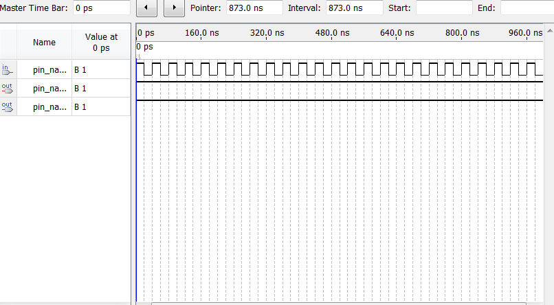
- Mark as New
- Bookmark
- Subscribe
- Mute
- Subscribe to RSS Feed
- Permalink
- Report Inappropriate Content
Synthesis is the act of turning a design into something that can run in hardware. Simulation is simulating the function of a design in a simulation tool. You can do a lot of things in a design for simulation that you can't do in a synthesizable design like define time delays, since time delays in hardware are determined by the hardware itself, not how you code it.
For synthesis, you could just write: if (rising_edge(dclk)) then gclk <= NOT gclk; end if;- Mark as New
- Bookmark
- Subscribe
- Mute
- Subscribe to RSS Feed
- Permalink
- Report Inappropriate Content
--- Quote Start --- Newbie here. I need to generate pulses at rising/falling edges of an input signal. I would like to avoid using an internal clock for this application because parts of my system is inherently asynchronous (for one thing, the clock used to count and do other things changes frequency in time). The width of the pulses is not important, I will not be sampling at more than 1Mhz. --- Quote End --- These are some strange design choices, and as a beginner, I would steer clear. Unless you know what you're doing, asynchronous systems are going to be a headache. WHy is the design asynchronous? why does the clock change frequency? You would have a much easier life if you synchronised the design to a single, stable clock. Apart from the fact this is how FPGAs are designed to work, you will have more tools and help at your disposal.
- Mark as New
- Bookmark
- Subscribe
- Mute
- Subscribe to RSS Feed
- Permalink
- Report Inappropriate Content
Thanks, these tips are helpful. I have a lot to learn about the language and field in general.
A number of flip-flops and a counter are clocked with a signal that changes frequency (so to speak): I research optics and am working on a new type of interferometer. I need to clock registers each time the distance between the reference and source signals changes by about 0.3 microns (1/2 HeNe laser wavelength). Since the reference signal is not always moving at constant speed, the time between the counts is not constant. Before diving into the FPGA, I have had success using discrete IC's, but for everything I need to do it gets bulky very fast and wiring can be a headache in the prototype phase (for the edge detection I used a one-shot 74221 IC, this is the step I am trying to emulate now, everything else in my program seems to get the job done). I am not an electrical engineer or computer scientist so I appreciate your feedback; turned out I needed custom electronics in my research so I've had to learn everything the hard way.- Mark as New
- Bookmark
- Subscribe
- Mute
- Subscribe to RSS Feed
- Permalink
- Report Inappropriate Content
You would probably be better off clocking the design on a single, higher speed clock, and synchronising these signals to the single clock. Then you can enable the count only when the distance changes externally.
- Mark as New
- Bookmark
- Subscribe
- Mute
- Subscribe to RSS Feed
- Permalink
- Report Inappropriate Content
So you are suggesting that I use the enable option for all flip-flops and counters, and enable with the function I am currently wrestling with? I can use the square wave (my input signal) to make a single count? I have no problem with that, but, as an amateur, I do not see how that will provide different results in practice (though I can see how I could use that to make synchronized pulses, which is why I have considered implementing something like this). Is this more reliable? Does this have something to do with the architecture of FPGA's and/or CPLD's? Thanks again.
- Mark as New
- Bookmark
- Subscribe
- Mute
- Subscribe to RSS Feed
- Permalink
- Report Inappropriate Content
Using a clock will make timing analysis much easier.
With random clocks, you cannot do timing analysis.- Subscribe to RSS Feed
- Mark Topic as New
- Mark Topic as Read
- Float this Topic for Current User
- Bookmark
- Subscribe
- Printer Friendly Page