- Mark as New
- Bookmark
- Subscribe
- Mute
- Subscribe to RSS Feed
- Permalink
- Report Inappropriate Content
Dear Altera Forum members...
This is my first post here :) I have a sub-circuit that consists of a binary up-counter (LPM_counter) with asynchronous reset and count enable, and a comparator (LPM_compare). The sub-circuit compares an input 5-bit vector to the count value and sets an output flag if the count value is greater-or-equal to the input data value. This flag is used as a control bit to a finite state machine. When running the TimeQuest timing analyzer tool in Quartus, I get setup timing violations with worst-case timing paths that involve the q[1]-bit and states of the FSM. My question is whether or not I can set these as false paths https://alteraforum.com/forum/attachment.php?attachmentid=14298&stc=1 The figure shows how the TimeQuest labels the nodes that violate the setup timing. I was thinking that since the timing violations does not involve the flag used to control the state transitions, I can set the shown paths as false paths... Please comment. Regards Ronny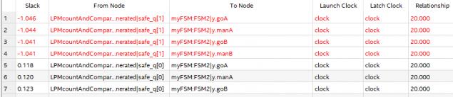
Link Copied
12 Replies
- Mark as New
- Bookmark
- Subscribe
- Mute
- Subscribe to RSS Feed
- Permalink
- Report Inappropriate Content
--- Quote Start --- Dear Altera Forum members... This is my first post here :) I have a sub-circuit that consists of a binary up-counter (LPM_counter) with asynchronous reset and count enable, and a comparator (LPM_compare). The sub-circuit compares an input 5-bit vector to the count value and sets an output flag if the count value is greater-or-equal to the input data value. This flag is used as a control bit to a finite state machine. When running the TimeQuest timing analyzer tool in Quartus, I get setup timing violations with worst-case timing paths that involve the q[1]-bit and states of the FSM. My question is whether or not I can set these as false paths https://alteraforum.com/forum/attachment.php?attachmentid=14298&stc=1 The figure shows how the TimeQuest labels the nodes that violate the setup timing. I was thinking that since the timing violations does not involve the flag used to control the state transitions, I can set the shown paths as false paths... Please comment. Regards Ronny --- Quote End --- Every path is relevant unless you the designer knows that it is not. Your clock is 50 MHz and in a modern fpga you shouldn't fail timing. likely you are clocking wrong. Or too long comb section
- Mark as New
- Bookmark
- Subscribe
- Mute
- Subscribe to RSS Feed
- Permalink
- Report Inappropriate Content
The chip is a MAX V 5M80ZM64I5 CPLD, not an FPGA.
- Mark as New
- Bookmark
- Subscribe
- Mute
- Subscribe to RSS Feed
- Permalink
- Report Inappropriate Content
Max v devices are really just FPGAs. They work basically the same.
As for this problem, you cannot set false paths as all are relevant.- Mark as New
- Bookmark
- Subscribe
- Mute
- Subscribe to RSS Feed
- Permalink
- Report Inappropriate Content
Thanks for responding
- Mark as New
- Bookmark
- Subscribe
- Mute
- Subscribe to RSS Feed
- Permalink
- Report Inappropriate Content
Hi kaz.
In your comment "likely you are clocking wrong", will you please elaborate what that means ? The clock is generated externally. It is defined using the "create_clock"-command in the sdc file... In another example, using a max V CPLD with vhld code of a circuit that involves an LPM_counter and an LPM_compare - connected to a very basic FSM, I still cannot close timing for a 100 MHz clock (Fmax = ~97 MHz)... Do you think my code is faulty ?- Mark as New
- Bookmark
- Subscribe
- Mute
- Subscribe to RSS Feed
- Permalink
- Report Inappropriate Content
Can you post code and your .sdc file?
- Mark as New
- Bookmark
- Subscribe
- Mute
- Subscribe to RSS Feed
- Permalink
- Report Inappropriate Content
Yes sure. Should I append text-files ?
- Mark as New
- Bookmark
- Subscribe
- Mute
- Subscribe to RSS Feed
- Permalink
- Report Inappropriate Content
why not post the code along with the .SDC file?
- Mark as New
- Bookmark
- Subscribe
- Mute
- Subscribe to RSS Feed
- Permalink
- Report Inappropriate Content
The project uses the MAX V 5M80ZM64I5 device.
There are three auto-generated VHDL files: lpmcompare.vhd, lpmcounter.vhd and lpmzerotimeflag.vhd. The lpmcountandcompare.vhd, connects them together as a subcircuit. The toplevel entity is the timingtest_lpmcc_minifsm.vhd. The .sdc file is called timingTest_LPMcc_miniFSM (there is only one constraint, the "create_clock"...) Recall that Quartus by default uses 3-space wide tabs, such that the text-files may not look that nice in other text-editors...- Mark as New
- Bookmark
- Subscribe
- Mute
- Subscribe to RSS Feed
- Permalink
- Report Inappropriate Content
--- Quote Start --- why not post the code along with the .SDC file? --- Quote End --- Would you rather that I copy-paste them into "reply"-fields, in the browser ? This will look messy...
- Mark as New
- Bookmark
- Subscribe
- Mute
- Subscribe to RSS Feed
- Permalink
- Report Inappropriate Content
The failing path is between the counter and state machine via the compare. Is it possible to pipeline the compare?
The Max devices are not very fast, so I can only assume the compare is a little too much in the path.- Mark as New
- Bookmark
- Subscribe
- Mute
- Subscribe to RSS Feed
- Permalink
- Report Inappropriate Content
--- Quote Start --- The failing path is between the counter and state machine via the compare. Is it possible to pipeline the compare? The Max devices are not very fast, so I can only assume the compare is a little too much in the path. --- Quote End --- Thank you so much. I appreciate the comment "the Max devices are not very fast"... Regarding pipelining, does this involve synchronizing the output of the compare to the clock, just prior to using as the FSM control signal ? I.e, connect it to the data port of a D flip-flop, and connect the output port of that same D flip-flop to the flag input port of the FSM ?
Reply
Topic Options
- Subscribe to RSS Feed
- Mark Topic as New
- Mark Topic as Read
- Float this Topic for Current User
- Bookmark
- Subscribe
- Printer Friendly Page