- Mark as New
- Bookmark
- Subscribe
- Mute
- Subscribe to RSS Feed
- Permalink
- Report Inappropriate Content
I have questions on the reference design for transceiver toolkit on cyclone 10 dev kit provided here: https://fpgacloud.intel.com/devstore/platform/17.1.1/Pro/cyclone-10-gx-xcvr-toolkit-reference-design/ . I am using Quartus prime 19.1, and I adapted the quartus design to use the usb type c instead of FMC connector since I don't have FMC loopback and our project is using usb type c.
When I sweep the PMA settings in transceiver toolkit, I see that the maximum BER is never above 0.015503. I remove the external loopback connector as stated in the pdf user guide (page 10) for this project and the BER is still never above 1.55% no matter how many times I reset counter/restart. I see that the lock is lost and the yellow highlights as expected on the user guide, but I would expect the BER to be close to 1 since there is no physical path for data to be sent. I also tried adapting the project to my hardware using Arria 10, and saw the BER was always 1.55%. In my hardware, using a third party IP, USB will enumerate through the type C so this always high BER is unexpected.
As of now, I am questioning the setup of enabling transceiver toolkit in the project, and I would like to know if a maximum BER of 1.55% is indicative of an issue with the design, or maybe issue with transceiver toolkit. I saw that in the example design IP settings, the enable reconfiguration and ADME in one of the IP components was not enabled and they are required based on https://www.intel.com/content/www/us/en/programmable/support/training/course/otcvrkita10.html
Enabling this or and the recommendations I found in transceiver PHY user guide did not fix my BER being maximum 1.5%. THe recommendations from PHY user guide: https://www.intel.com/content/www/us/en/programmable/documentation/hki1486507600636.html
"To enable Intel® Cyclone® 10 GX transceiver toolkit capability in the Native PHY IP core, you must enable the following options:
- Enable dynamic reconfiguration
- Enable Altera Debug Master Endpoint
- Enable capability registers
- Enable control and status registers
- Enable PRBS (Pseudo Random Binary Sequence) soft accumulators"
I implemented second option here:
"Note:When you enable ADME in your design, you must
- connect an Avalon-MM master to the reconfiguration interface
- OR connect the reconfig_clock,reconfig_reset signals and ground the reconfig_write, reconfig_read, reconfig_address and reconfig_writedata signals of the reconfiguration interface. If the reconfiguration interface signals are not connected appropriately, there will be no clock or reset for the ADME and ADME will not function as expected"
Link Copied
- Mark as New
- Bookmark
- Subscribe
- Mute
- Subscribe to RSS Feed
- Permalink
- Report Inappropriate Content
- Mark as New
- Bookmark
- Subscribe
- Mute
- Subscribe to RSS Feed
- Permalink
- Report Inappropriate Content
Hi Dlim,
I don't want a BER>1.5E-2, my custom hardware is always showing a BER of 1.5E-2. I am wondering what this means since I observe that in Cyclone 10 dev kit, I never see BER above 1.5E-2, it maxes out at 1.5E-2, and I find that strange.
Yes, I see "number of bits tested" increase and "number of error bits" increase. The BER number does not seem to increment, it starts at 1.5E-2 on my hardware and stays there.
On the cyclone 10 dev kit, I tried without loopback and then reset checker to recalculate the BER, and it is still 1.5E-2. Since there is no physical connection, I would expect the result to be number of bits test=number of error bits for a BER of 1, but unexpectedly I get 1.5E-2.
Now the question is, is 1.5E-2 just the maximum BER for transceiver toolkit for some reason? Or is there maybe a problem with my quartus project when I ported it? From your response, it seems like if there was a problem during port, the toolkit would not activate BER at all.
When you test the transceiver toolkit, can you disconnect the loopback and reset the checker, does the BER go to 1 or 1.5E-2?
Thanks
Chenxi
- Mark as New
- Bookmark
- Subscribe
- Mute
- Subscribe to RSS Feed
- Permalink
- Report Inappropriate Content
- Mark as New
- Bookmark
- Subscribe
- Mute
- Subscribe to RSS Feed
- Permalink
- Report Inappropriate Content
- Mark as New
- Bookmark
- Subscribe
- Mute
- Subscribe to RSS Feed
- Permalink
- Report Inappropriate Content
Hi Dlim,
Thank you for the help so far. It seems like BER of 1.5E-2 is some sort of upper limit.
As for my custom hardware, I think the reason it was giving me BER of always 1.5E-2 was an hardware issue. I found that a differential pair was swapped positive and negative, which the third party IP which implements the protocol automatically handles polarity swap. However, their IP did not have an ADME option to enable the transceiver toolkit so I was using the Cyclone 10 reference design which can't handle polarity swap. After I implement a workaround, I see a much lower BER, and sweeping the settings changes BER.
However, the color indicator behavior is still a bit confusing to me. When I disconnect the loopback, the indicator will sometimes still remain green, even though there is no physical path from TX to RX, even though BER will become 1.5E-2. When I was testing earlier with the swapped polarity and BER stuck at 1.5E-2, the indicator was green with a loopback connected. I see that your screenshot, you also have the indicator green with 1.5E-2 BER. I think it might have something to do with the options in Transceiver Native PHY IP under Standard PCS tab"Number of word alignment patterns to achieve sync", "number of invalid data words to lose sync, "number of valid data words to decrement sync". I haven't figured out how to change these yet without getting an error
Best regards
Chenxi
- Mark as New
- Bookmark
- Subscribe
- Mute
- Subscribe to RSS Feed
- Permalink
- Report Inappropriate Content
- Mark as New
- Bookmark
- Subscribe
- Mute
- Subscribe to RSS Feed
- Permalink
- Report Inappropriate Content
Hi Dlim,
Thanks for your response. Some urgent tasks came up, and I have been a bit busy lately, but now I will begin to pick this up again. In my tests, most of the time, the indicator is correct, meaning when I disconnect loopback, it will alternate between green and yellow. However, in some cases it will stay green always, and not turn to yellow, when loopback is disconnected after running the transceiver toolkit. It seems to depend on the cable length used and PRBS pattern selected. I have not yet narrowed down exactlywhen it occurs, but it seems to happen more for smaller PRBS (e.g. PRBS7)and shorter cables.
In cases where this happens, the indicator will be yellow , and correct if the transceiver toolkit is started without a loopback, and will turn green when loopback connector is hot-plugged in. Then, when I disconnect the loopback, the toolkit still shows the CDR lock always green. When this happens seem to depend on which PRBS setting I choose and which length cable I use. Also, i believe that with the reversed differential pair polarity would always behave like this, though I would need to double check that.
For my earlier question of why BER was stuck at 1.55E-2, I am still a bit confused by the explanation that it is BER counter limit, because if I keep running transceiver toolkit, the number of error count still goes up, so that would imply counter didn't reach a limit. The BER result also seems to agree with error counter, are they separately counted, or calculated from each other. Is there any documentation of the transceiver toolkit error counter limits?
Thanks
Chenxi Dai
- Mark as New
- Bookmark
- Subscribe
- Mute
- Subscribe to RSS Feed
- Permalink
- Report Inappropriate Content
- Mark as New
- Bookmark
- Subscribe
- Mute
- Subscribe to RSS Feed
- Permalink
- Report Inappropriate Content
Hello dlim,
Thanks for the reply. I am using the TTK for tuning transceiver, but I have been trying to use the green/yellow indicator to check if hardware for transceiver link is set up. We are using the transceiver for USB and it goes off the pcb board via USB cable, and I also made a few loopback connectors, some with polarity swap and others normal loopback.
I have double checked that reversing the differential pair polarity will always result in a green indicator, both in the Cyclone 10 dev kit, and in our hardware, and regardless of Test Pattern, and cable/loopback connector used. Since this green/yellow indicator does not seem to be always accurate, I don't think we can rely on it to tell if our transceiver hardware is set up properly. The workaround seems to be to check BER, if it is 1.55E-2, then double check the hardware setup. E.g. for us, check loopback connector is right differential pair polarity for the hardware (our hardware has polarity swap on the PCB), and/or cable, then check PCB board and circuits on it.
- Mark as New
- Bookmark
- Subscribe
- Mute
- Subscribe to RSS Feed
- Permalink
- Report Inappropriate Content
Hi ChenXi,
Understood your use case but as I explained earlier. Don't rely on ttk green/yellow light indicator as it's not accurate.
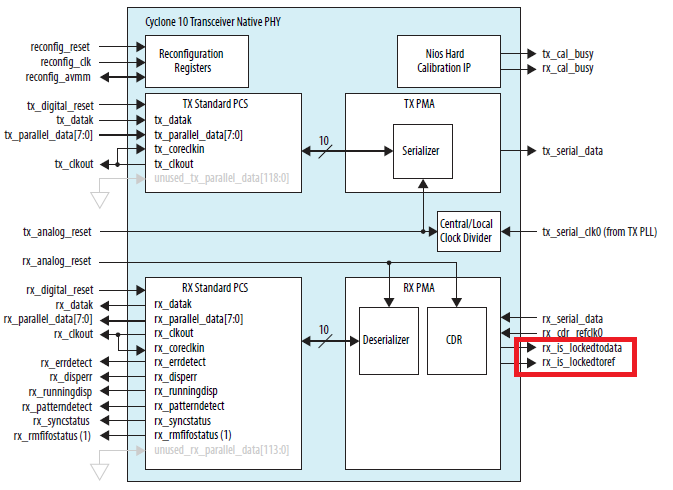
The recommended way is to check the rx_is_lockedtodata or rx_is_lockedtoref to really tell whether CDR loose lock or not as shown in attached diagram.
Thanks.
Regards,
dlim
- Subscribe to RSS Feed
- Mark Topic as New
- Mark Topic as Read
- Float this Topic for Current User
- Bookmark
- Subscribe
- Printer Friendly Page