- Mark as New
- Bookmark
- Subscribe
- Mute
- Subscribe to RSS Feed
- Permalink
- Report Inappropriate Content
Hi all,
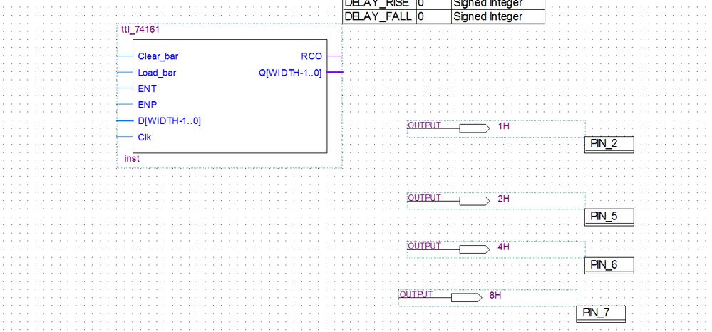
I need to implement a 4-bit counter (74161) in my schematics, I found a Verilog example but I'm unable to properly wire the symbol because it uses bus for inputs and outputs.Specifically I need to label the outputs in a certain way (because they are outputs from the CPLD and they must be labeled as H1, H2, H2, H4) while the four input must be tied to GROUND.How can I obtain this?
Here's the piece of code :
module ttl_74161 #(parameter WIDTH = 4, DELAY_RISE = 0, DELAY_FALL = 0)
(
  input Clear_bar,
  input Load_bar,
  input ENT,
  input ENP,
  input [WIDTH-1:0] D,
  input Clk,
  output RCO,
  output [WIDTH-1:0] Q
);

//------------------------------------------------//
wire RCO_current;
reg [WIDTH-1:0] Q_current;
wire [WIDTH-1:0] Q_next;

assign Q_next = Q_current + 1;

always @(posedge Clk or negedge Clear_bar)
begin
  if (!Clear_bar)
  begin
    Q_current <= {WIDTH{1'b0}};
  end
  else
  begin
    if (!Load_bar)
    begin
      Q_current <= D;
    end

    if (Load_bar && ENT && ENP)
    begin
      Q_current <= Q_next;
    end
  end
end

// output
assign RCO_current = ENT && (&Q_current);

//------------------------------------------------//

assign #(DELAY_RISE, DELAY_FALL) RCO = RCO_current;
assign #(DELAY_RISE, DELAY_FALL) Q = Q_current;

endmodule
Thanks in advance.
Link Copied
- Mark as New
- Bookmark
- Subscribe
- Mute
- Subscribe to RSS Feed
- Permalink
- Report Inappropriate Content
Here is how the code looks compiled into a symbol.H1, H2, H4, H8 must be the outputs from it (H1 the first bit, H8 the last one)
- Mark as New
- Bookmark
- Subscribe
- Mute
- Subscribe to RSS Feed
- Permalink
- Report Inappropriate Content
You just attach wires and label them appropriately to break out the bits of the bus: Q[3], Q[2], Q[1], and Q[0].
- Mark as New
- Bookmark
- Subscribe
- Mute
- Subscribe to RSS Feed
- Permalink
- Report Inappropriate Content
Can you, please, explain it in schematics?Sorry but this is the firt time I use bus, I always used symbols with individual input/output lines.Thanks.
- Mark as New
- Bookmark
- Subscribe
- Mute
- Subscribe to RSS Feed
- Permalink
- Report Inappropriate Content
I came to conclusion that, using that symbol with the bus, I'm forced to label the outputs as Q[0], Q[1], Q[2], Q[3].This is not what I wanted.I need to label them in a different way.Is this possible?
- Mark as New
- Bookmark
- Subscribe
- Mute
- Subscribe to RSS Feed
- Permalink
- Report Inappropriate Content
You're using the bus tool (thick line) instead of the wire tool (thin line). And you changed the names of the outputs. If you want the H names like you mentioned, change the output names back the way you had them and then attach wires to the 4 outputs and label them as I said to make the connections.
Or since you already have the HDL code, just use that as the top level in your project instead of creating a schematic at all.
- Mark as New
- Bookmark
- Subscribe
- Mute
- Subscribe to RSS Feed
- Permalink
- Report Inappropriate Content
Caius,
May I know if there is any update?
- Subscribe to RSS Feed
- Mark Topic as New
- Mark Topic as Read
- Float this Topic for Current User
- Bookmark
- Subscribe
- Printer Friendly Page

