- Mark as New
- Bookmark
- Subscribe
- Mute
- Subscribe to RSS Feed
- Permalink
- Report Inappropriate Content
Hi everybody
I am new to NIOS and has been learning how to control a system but is encountering some difficulties. I have added a VGA system to the NIOSII system and is trying to verify if it's working by outputting "Hello world". The strings hello world is stored in a RAM which has its own memory map in the VGA system. when trying to run in C, I got really confused at this point.. Since I am writing to this RAM, the address it takes is definitely different from the base address of the entire VGA system added. eg. The 'H' char is stored at address 9203 of the RAM. but the base address of the peripheral is 0x01800000 (VGA_BASE , from system.h) Could anyone please give me a hint to how to write to the address of the RAM that I am interested in ? Thank you !Link Copied
- Mark as New
- Bookmark
- Subscribe
- Mute
- Subscribe to RSS Feed
- Permalink
- Report Inappropriate Content
Just add the offset to the base address of the memory area.
There are a variety of ways of doing it, you also probably want to bypass any data cache as well. Personally I would use a C structure (or maybe an array in this case) that describes the IO locations and either set a C pointer to the address (0x81800000 to get cache bypass) or get the linker to assign the absolute address to a symbol.- Mark as New
- Bookmark
- Subscribe
- Mute
- Subscribe to RSS Feed
- Permalink
- Report Inappropriate Content
Thank you!
I tried to use the function IOWR_32DIRECT(VGA_BASE,offset,'H'); to see if I can write H to address 9203 but had no luck.. I will try to use pointer but isnt the pointer doing the same thing as the above function? Thank you again.- Mark as New
- Bookmark
- Subscribe
- Mute
- Subscribe to RSS Feed
- Permalink
- Report Inappropriate Content
Probably - that function will expand to a 'stio', but I'm not sure how the offset is applied.
In particular you (probably) want to do a byte write, not a 32bit write and the 'offset' might be being multiplied by 4. You actually want a 'stbio' to address 0x1809203, or a 'stb' to address 0x81809203.- Mark as New
- Bookmark
- Subscribe
- Mute
- Subscribe to RSS Feed
- Permalink
- Report Inappropriate Content
For IOWR_32DIRECT the offset field is in bytes. So to perform sequential 32-bit accesses you would use offsets such as 0, 4, 8, 12, etc... Using IOWR_32DIRECT you also need to make sure that the address you are accessing is on a 4 byte boundary since Nios II and the interconnect do not support unaligned accesses.
Address 9203 is not aligned to a 4 byte boundary so you'll need to break that write access down like DSL suggested. You can use IOWR_8DIRECT to write individual byte lanes at any alignment assuming the slave you are accessing has byte enables. If it doesn't have byte enables then the byte access will have side effects if the slave port is wider than 8 bits.- Mark as New
- Bookmark
- Subscribe
- Mute
- Subscribe to RSS Feed
- Permalink
- Report Inappropriate Content
Thanks for the heads-up, really appreciated!
If I understand it correctly, can I say that since NIOS access peripheral registers in memory map only every 4 bytes(32bits) I could only access location 9216 in my memory map with IOWR(VGA_BASE, 288, data); // offset = the"nth" 32bits in the map for 9216/32=288 but never could access location 9203 like IOWR(VGA_BASE, x , data); //since 9203 can never be divided by 32, it is not aligned. And therefore I have to use pointer to access those individual registers. Please correct me if I am wrong. Thank you! ps. I have attached a memory map I am refering to for easier reference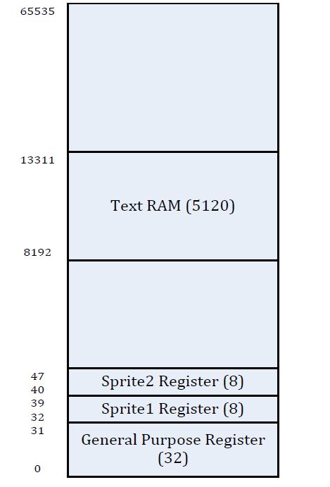
- Mark as New
- Bookmark
- Subscribe
- Mute
- Subscribe to RSS Feed
- Permalink
- Report Inappropriate Content
Think of alignment in bytes instead of bits. In your original post you where using a 32-bit write macro which requires 4 byte alignment. So when accessing a slave port that contains 32-bit registers you would access them using 4 byte aligned addresses such as 0, 4, 8, etc....
IOWR is a little different. It performs 32-bit accesses too but the offset field is in terms of 4 byte words. So IOWR_32DIRECT uses offsets such as 0, 4, 8, etc... but using IOWR you would use offsets 0, 1, 2, etc... to access the same locations. This can become confusing so I recommend sticking to one type of macros. I personally prefer IOWR_32DIRECT over IOWR since I find it necessary to use IOWR_8DIRECT and IOWR_16DIRECT which there is no equivalent using IOWR. So using the "direct" macros you control the size of the access and always use a byte offset. For _8DIRECT you can use any alignment and with _16DIRECT you use 2 byte alignment. 9203 was not aligned for use by IOWR_32DIRECT because it is not divisible by 4. To write a single byte to offset 9203 you would use IOWR_8DIRECT. Now be careful doing this, if the slave port you are accessing doesn't contain byteenables you might need to perform a read-modify-write to avoid sideeffects. If the slave is 32-bit and doesn't use byte enables writing a byte to address 9203 will cause addresses 9200-9202 to become written with zeros. If this is the case you might be able to read all four bytes, modify the upper byte, then write the full 32-bit word back out to address 9200.- Mark as New
- Bookmark
- Subscribe
- Mute
- Subscribe to RSS Feed
- Permalink
- Report Inappropriate Content
Thank you!
I think I have sort of got the picture now. The Avalon address signal actually represents "how many 4bytes are there " rather than just normal address. eg. ADDR[2:0] mapping into a 8 bits memory-map RAM would not just address my RAM from its BASE to BASE+7 but actually, it means to provide 8 segments of address in which each segment contains 4 bytes. If the data in a register does not have 4 bytes, eg. 2 bytes, the remaining 2 bytes address is reserved to keep the alignment up. Hence, the actual RAM address would start from BASE to BASE+8*32. And in this case I can access the SAME register using different addresses eg. The first register has a data width of 2 bytes and I can access that particular register at any address ranging from BASE+0 to BASE+0xFF, but in the next 2 byes range from 0xFF to 0xFFFF I will simply get nothing. Then after 0xFFFF, I will be accessing the 2nd register and so on. Please correct me if my understanding is any slightly wrong Thank you!- Mark as New
- Bookmark
- Subscribe
- Mute
- Subscribe to RSS Feed
- Permalink
- Report Inappropriate Content
Historically Avalon addresses from a master have always been byte addresses aligned to whatever the width of the master is. Slaves on the other hand used word addresses where each address represents a byte, 2 bytes, 4 bytes, etc... depending on the width of the slave port. In the new Avalon spec which Qsys relies on you can use word or byte addressing for masters and slaves so it is a bit more flexible.
At the end of the day if you use the direct macros and always use byte address offsets (with the appropriate alignment) then you should have consistent accesses to the memory space and not have to worry about what the underlining hardware is doing. To access two bytes at the beginning of a slave base address you would use something like IOWR_16DIRECT(base, 0, data). To access the next two bytes you would use IOWR_16DIRECT(base, 2, data). I believe you are getting confused by bits and bytes, forget about the bits, the only thing they impact is the alignment you need to use. 8, 16, and 32-bit data requires 1, 2, and 4 byte alignment.- Mark as New
- Bookmark
- Subscribe
- Mute
- Subscribe to RSS Feed
- Permalink
- Report Inappropriate Content
An alternative view is that the nios2 accesses avalon slave peripherals in much the same way as any 32bit micro. The two low address bits (often called A0 and A1) are converted into 4 byte enable lines, the remaining address lines are use to select the actual device and register (etc).
So if you want to do a byte write, the actual bus write cycle only has 1 of the 4 byte enables asserted. A single cpu instruction can also only generate 1 (32bit) bus cycle, so you can't do misaligned accesses (ie read a 32bit word from an odd address). There are a couple of things that complicate matters: 1) Bus width adapters. If you define an avalon slave with only 8 bit data, the system inserts logic to convert the 32bit cycle generated by the nios into four 8bit cycles to your slave. Although useful when connecting narrow memory, for IO it is rather a PITA and it is best to make your avalon slave a 32bit slave by returning 0 for all the high data bits. I don't know how the 32->8 bit bus adapter works, but the one that converts 64->32 bits (used in the PCIe slave) generates cycles with no byte enables asserted! 2) The nios cpu always asserts all 4 byte enables on reads, and discards the unwanted bytes internally.- Mark as New
- Bookmark
- Subscribe
- Mute
- Subscribe to RSS Feed
- Permalink
- Report Inappropriate Content
Thank you for the information.
They are really helpful! I have successfully written the data to the desired addresses finally.. The "HELLO WORLD" appears right where expected but it's interesting to see that there were data written on random addresses in the memory map at the same time. Eg. In the screenshot there are random characters besides HELLO WORLD .. I've spent quite a long time looking into it but cannot really locate the problem, could it be more subtle or is there anything obvious I am overlooking ..? ps. My data bus is 32 bits ( [31:0] )but I am only using the last 8 bits( [7:0] ) to write into my memory block since the data width in memory are 8 bits. Thank you again!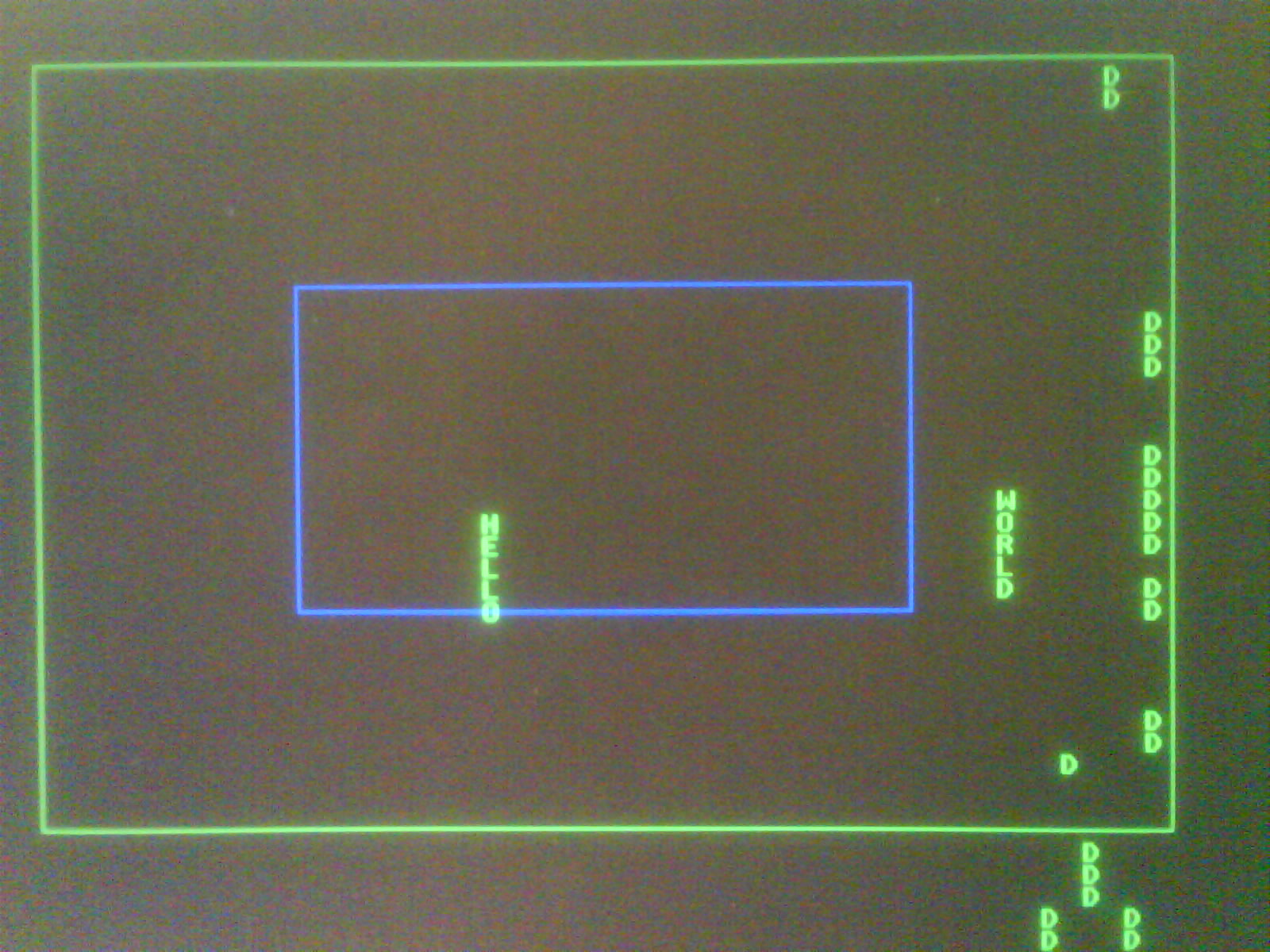
- Mark as New
- Bookmark
- Subscribe
- Mute
- Subscribe to RSS Feed
- Permalink
- Report Inappropriate Content
I would switch to the debugger and watch your code flow while it is drawing to the frame buffer. I have no idea what could be going wrong since I've never used the IP you are using.
- Mark as New
- Bookmark
- Subscribe
- Mute
- Subscribe to RSS Feed
- Permalink
- Report Inappropriate Content
I'd also try to see when the values are written.
It is 'interesting' that all the errors are 'D'! It might be that your Avalon slave isn't correctly decoding the timing of all the signals - so is seeing signals from the bus cycles either side of the one you should be looking at.- Subscribe to RSS Feed
- Mark Topic as New
- Mark Topic as Read
- Float this Topic for Current User
- Bookmark
- Subscribe
- Printer Friendly Page