- Mark as New
- Bookmark
- Subscribe
- Mute
- Subscribe to RSS Feed
- Permalink
- Report Inappropriate Content
Hello,
I"m trying to get the flash chip on the DE2-115 Terasic board up and running. I've read through the documentation for the CFI peripheral which I select in the Generic Tri-state controller. This is on the right under the presets section. I then put in my signal timing on the signal timing tab. The problem I'm having is that when I compile this design in Quartus I don't have the same control lines as the flash chip schematics show. For example, the chip has a reset control line which I don't have and it has a write protect control line which I don't have. There is a section underneath the "Enable the following signals" text on the signal selection tab and I guess I could check "reset output", but I"m not sure if this is correct. Even if it is there is still no option for write protect. I found CFI flash memory configuration examples in the web server demonstration, but that is even more confusing because in that demonstration they look like they use the default settings, only add in the signal timing (which I copied since it's the same board) and when I compile the web server demo and look at pin planner their names are the same as the schematic net names and theyhave ALL of the control signals. How is this possible? How do I get all the control signals for the on board flash for the DE2-1115 board? Here is a pic of my Tri-state controller: http://www.alteraforum.com/forum/attachment.php?attachmentid=9457&stc=1 Here is a pic of my pin planner: http://www.alteraforum.com/forum/attachment.php?attachmentid=9458&stc=1 Here is a screen of the schematics for the flash chip: http://www.alteraforum.com/forum/attachment.php?attachmentid=9459&stc=1 It seems like the Tristate controller just doesn't produce all of those signals, but some how everything is there in the webserver demo and it's named exactly as the net names in the schematics, not the signal names form Qsys. Does anyone know whats going on here?Link Copied
- Mark as New
- Bookmark
- Subscribe
- Mute
- Subscribe to RSS Feed
- Permalink
- Report Inappropriate Content
Reset and Write Protect are not strictly part of the flash interface. Infact, they are not involved in data access, but they are rather asynchronous signals used for special device functions. Usually you drive them with a gpio, so they are not included in the flash controller.
- Mark as New
- Bookmark
- Subscribe
- Mute
- Subscribe to RSS Feed
- Permalink
- Report Inappropriate Content
Ok. I'll give that a shot. Makes sense I just wasn't sure what was going on there.
- Mark as New
- Bookmark
- Subscribe
- Mute
- Subscribe to RSS Feed
- Permalink
- Report Inappropriate Content
Hey so should I enable output enable on the Tristate controller? My flash part has an OE pin and I noticed that the tristate controller has a checkbox for that signal. It isn't checked, but I'm assuming I should check it and connect that pin to the OE on flash part? If so, that leaves me with only RST and WP left over which can just be set high on PIO like you mentioned.
- Mark as New
- Bookmark
- Subscribe
- Mute
- Subscribe to RSS Feed
- Permalink
- Report Inappropriate Content
So I finally got this working. I'm not sure why doing this triggered it but I think all I did after applying the above ideas was add the pin sharer (even though I'm not sharing any pins) and changed this
fd = alt_flash_open_dev(CFI_FLASH_CONTROLLER_NAME); to this (basically replacing the define with the text it was defining "/dev/CFI_Flash_Controller" And all of a sudden it worked. The code I ran was this:
	//
	// Setup Flash
	//
	IOWR_ALTERA_AVALON_PIO_DATA(PIO_3_BASE,0xC0);
	fd = alt_flash_open_dev(CFI_FLASH_CONTROLLER_NAME);
	if(fd != NULL){
		printf("Flash recognized!\n");
		printf("0x%x \n", fd);
	}else{
		printf("Flash device not recognized!\n");
		printf("0x%x \n", fd);
	}
Because initially I just wanted to see if I could open the devices. It looks like it's working I've run this:
	//
	// Setup Flash
	//
	IOWR_ALTERA_AVALON_PIO_DATA(PIO_3_BASE,0xC0);
	fd = alt_flash_open_dev(CFI_FLASH_CONTROLLER_NAME);
	if(fd != NULL){
		printf("Flash recognized!\n");
		printf("0x%x \n", fd);
	}else{
		printf("Flash device not recognized!\n");
		printf("0x%x \n", fd);
	}
	// Test Flash memory
	ret_code = alt_write_flash(fd, 0, source, BUFF_SIZE);
	printf("Write return code: 0x%x \n", ret_code);
	ret_code = alt_read_flash(fd, 0, dest, BUFF_SIZE);
	printf("Read return code: 0x%x \n", ret_code);
	alt_flash_close_dev(fd);
	printf("Flash device closed! \n");
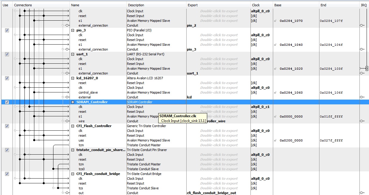
And everything checks out in that the functions return 0x00 and in debug mode my dest buffer has 0xAA's in it. I found this document that was somewhat helpful as well. http://www.altera.com/literature/hb/nios2/n2sw_nii5v2.pdf My Qsys config looks like this https://www.alteraforum.com/forum/attachment.php?attachmentid=9462 Maybe this will help someone else out.
- Subscribe to RSS Feed
- Mark Topic as New
- Mark Topic as Read
- Float this Topic for Current User
- Bookmark
- Subscribe
- Printer Friendly Page