- Mark as New
- Bookmark
- Subscribe
- Mute
- Subscribe to RSS Feed
- Permalink
- Report Inappropriate Content
Hello,
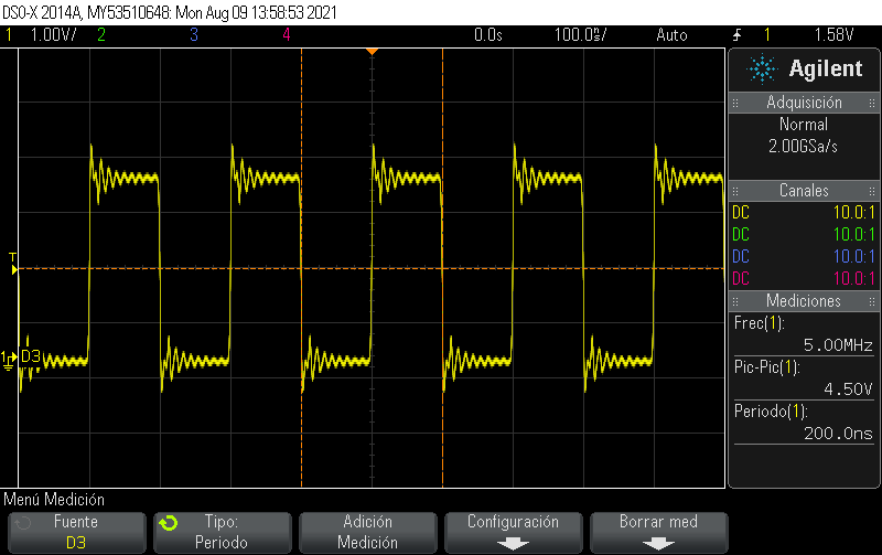
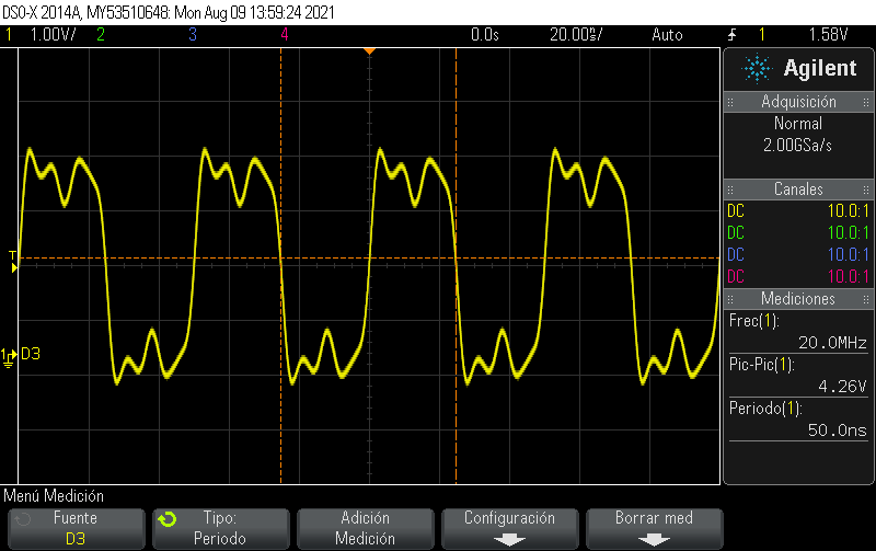
I'm working with the DECA board, I'm using the Basic Function to generate a PLL with the ALTPLL tool. Everything works fine with lower frequency from 1kHz-1MHz, the problem stars when I'm trying to generate higher frequency like 5MHz to 100MHz, the input clock is the base clock of 50MHz.
For the higher frequency the distortion of the square signal start to figure out as a sinusoidal signal, I attach different reference image from the oscilloscope for the distortion signal at different high frequencies.
I want to know if this is a normal behavior of the DECA board, or I'm messing any additional configuration, I base on documentation "1_FPGA_Intro_Lab" from the DECA board to configure the ALTPLL
Link Copied
- Mark as New
- Bookmark
- Subscribe
- Mute
- Subscribe to RSS Feed
- Permalink
- Report Inappropriate Content
Hello,
I see that this query was left unattended. Do you still need support on this or were you able to resolve on your own?
Regards
- Mark as New
- Bookmark
- Subscribe
- Mute
- Subscribe to RSS Feed
- Permalink
- Report Inappropriate Content
Putting my thought anyway.
What compensation mode did you use?
Check if you are driving the PLL output clock to a FPGA pin which is creating some contention on board? Try assigning to other pin.
Check the clock internally using Signal Tap Analyzer.
Regards
- Mark as New
- Bookmark
- Subscribe
- Mute
- Subscribe to RSS Feed
- Permalink
- Report Inappropriate Content
This thread will be transitioned to community support. If you have a new question, feel free to open a new thread to get the support from Intel experts. Otherwise, the community users will continue to help you on this thread. Thank you
- Subscribe to RSS Feed
- Mark Topic as New
- Mark Topic as Read
- Float this Topic for Current User
- Bookmark
- Subscribe
- Printer Friendly Page