- Mark as New
- Bookmark
- Subscribe
- Mute
- Subscribe to RSS Feed
- Permalink
- Report Inappropriate Content
We have a PCB designed around an Arria 10 10AX032H4F35E3SG and are seeing poor rising edges on all 1.8v banks across the chip. The 3.0v bank (running at 3.0v) is not showing any issue - nor is the Arria 10 SoC dev board.
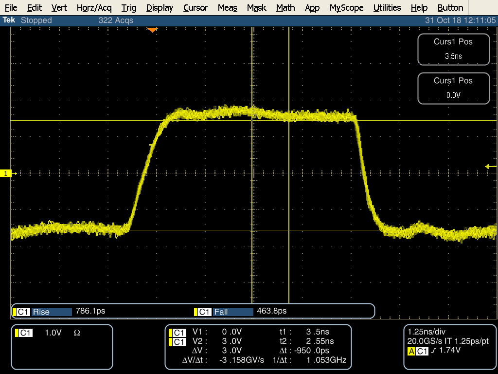
The poor rising edge generally consists of a fast-rising edge to around half the voltage, then a slow rise to 1.8v. This is far worse on longer tracks (more of a step), but we can see it even on unused FPGA pins for which we just happen to have a via letting us connect to it (i.e. near-zero track length).
Our outputs are 50 Ohm uncalibrated and tracks are all of 50 Ohm impedance and we have plenty of experience in getting this right. The falling edge is always fine. We've checked all power pins and none are dipping. Even with just 2 pins toggling on the 1152-pin FPGA we still see the issue.
This is confusing as well as concerning and any thoughts on what might be causing this are welcome. I've attached some 'scope shots.
a10_1.8v_at_pin = toggling 1.8v under the FPGA pin, no track connected.
a10_3.0v_at_pin = toggling 3.0v under the FPGA pin, no track connected.
a10_1.8v_5cm_track = toggling 1.8v after 5cm of track (unterminated).
a10_soc_dev_1.8v_10cm_track = toggling 1.8v after 10cm of track on our SoC dev board (unterminated).
Thanks,
Richard
Link Copied
- Mark as New
- Bookmark
- Subscribe
- Mute
- Subscribe to RSS Feed
- Permalink
- Report Inappropriate Content
Hi Richard,
The problem seems to be PCB /track loss of signal, from the hardware perspective you can check the power is fine or not to that particular bank.
And I am also recommend to use IBIS simulation to check whether the trace length support the signal integrity.
Regards,
RS
- Mark as New
- Bookmark
- Subscribe
- Mute
- Subscribe to RSS Feed
- Permalink
- Report Inappropriate Content
Hi Like,
I can confirm that this is not PCB / track loss, or a power problem. I've performed a whole load of other tests and communicated these to our Intel supplier and so will give a quick update here.
One of them measured the issue under the pin of the FPGA (track length < 1mm + a via), where it was still seen - this is the "a10_1.8v_at_pin" image from my first post, with the poor rising edge.
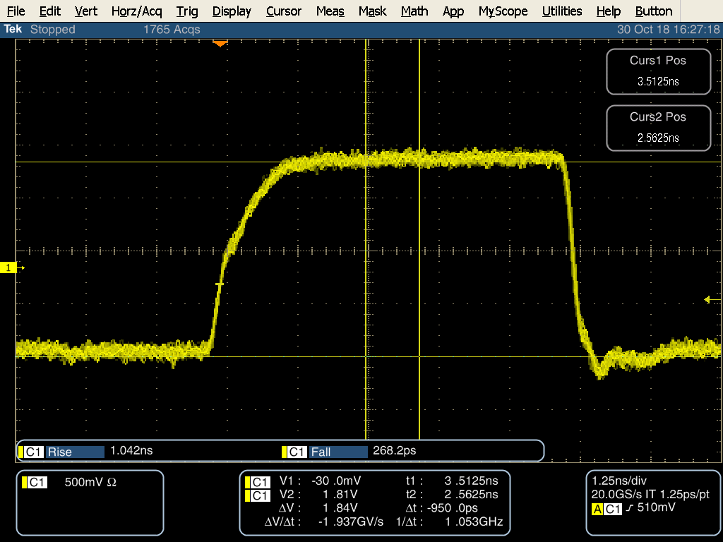
My latest test is to compare that same pin using the 50 Ohm Uncalibrated vs. Calibrated options. These two 'scope traces are attached and make it very clear that it's NOT a PCB or power issue. The Calibrated option is spot-on with a perfect rising edge. Uncalibrated gives poor results at the pin and are unusable on longer tracks.
From what I can see, Quartus is setting the wrong pull-up current strengths for the 10AX032 device we're using.
Please take a look at the attached 'scope shots and let me know what you think.
a10_1.8v_at_pin = Copy of previous test. Uncalibrated, toggling 1.8v under the FPGA pin, no track connected (just <1mm track + via).
a10_1.8v_at_pin_calibrated = exactly the same, but using the Calibrated option and a 100 Ohm RZQ resistor & OCT block.
Thanks,
Richard
- Mark as New
- Bookmark
- Subscribe
- Mute
- Subscribe to RSS Feed
- Permalink
- Report Inappropriate Content
- Subscribe to RSS Feed
- Mark Topic as New
- Mark Topic as Read
- Float this Topic for Current User
- Bookmark
- Subscribe
- Printer Friendly Page