- Mark as New
- Bookmark
- Subscribe
- Mute
- Subscribe to RSS Feed
- Permalink
- Report Inappropriate Content
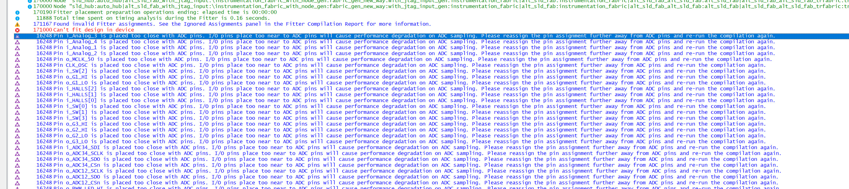
I have a 10M08SA design that is about 80% full. Board level power supplies are being measured by the FPGA's ADC's. However, when I compile the design, synthesis fails and the indication is that almost all the pins that are in use need be ununsed. This is quite bad. I understand the analog design considerations, but it appears that the ADC's are rather weak in terms of their applicable use.
Link Copied
- Mark as New
- Bookmark
- Subscribe
- Mute
- Subscribe to RSS Feed
- Permalink
- Report Inappropriate Content
- Mark as New
- Bookmark
- Subscribe
- Mute
- Subscribe to RSS Feed
- Permalink
- Report Inappropriate Content
You might get round this by using the 'I/O Maximum Toggle Rate' attribute in the Assignment editor. Add this attribute to each signal in question and set its value to 0. This may tell (fool) Quartus into believing this signal will not cause any interference on the analogue signal.
Note: this will risk additional noise on the analogue signal if these digital signals are not (relatively) static.
Tip: add this parameter for one signal. Then edit the project's .qsf file adding a similar entry for each signal in question.
Cheers,
Alex
- Mark as New
- Bookmark
- Subscribe
- Mute
- Subscribe to RSS Feed
- Permalink
- Report Inappropriate Content
Alex thanks for the feedback on this. I will try this and see what happens.
- Subscribe to RSS Feed
- Mark Topic as New
- Mark Topic as Read
- Float this Topic for Current User
- Bookmark
- Subscribe
- Printer Friendly Page