- Mark as New
- Bookmark
- Subscribe
- Mute
- Subscribe to RSS Feed
- Permalink
- Report Inappropriate Content
Hello,
have an Intel chassis SC5299WS with a S5000XVNSATAR M/B and 6 drive SATA cage model D22808-203 ( FXX6DRV3GBRD ) . I tried to update the HSC firmware under WINPE, loaded the drivers with success, used the FWPIAUPD utility with " -u filename " answered yes to the boot block ( which might be the issue ) and waited about 15 minutes to finish uploading the new firmware, success at the end. At restart HSC firmware in BIOS it's 0.00 and if i try to communicate with the backplane i get error no device...in the frusdr utility , the same " no backplane detected " . Trying to run the update program again has no effect because no comm's can be established. The cables from the backplane to the M/B are correctly connected. I observed on the backplane that there are 2 firmware chips ... 1 it's an 24c64wp which is a 64-Kbit serial I2C bus EEPROM and another SPI 1MB EEPROM.
What could have gone wrong and what chips it's the update utility accessing ? are these both chips written ? I have the posibility of manually programming these chips but i need to know which one of them are written by the hsc firmware update utility ! or if there are other solutions please let me know.
However the server it's booting fine, sees all drives, i presume that only the hot swap feature it's affected , or ?
Thank you very much.
Alex.
Link Copied
- Mark as New
- Bookmark
- Subscribe
- Mute
- Subscribe to RSS Feed
- Permalink
- Report Inappropriate Content
We understand that during the FRUSDR update it says no backplane detected. We would like to know how many backplanes do you have connected to the system and to which headers do you have the cable connected in both ends?
Best Regards,
Steven V.
- Mark as New
- Bookmark
- Subscribe
- Mute
- Subscribe to RSS Feed
- Permalink
- Report Inappropriate Content
Hi Steven,
I have one 6 drive backplane connected as follows :
SGPIO connector to SGPIO header on the M/B
IPMI connector to HSBP A header
SES ( on the enclosure ) to IPMI header on the M/B
Backplane was detected before the upgrade to 2.14 from 2.02 in the same configuration of the connectors from the backplane to the M/B, however when trying to complete the FRU set-up ( with backplane ver. 2.02 ) i encountered an error about header mismatch in the eeprom from C0 ( the backplane primary ) compared to the file i was trying to write and it never wrote the eeprom at C0 ( primary backplane). The board serial no and all the rest of the info were correctly transferred at address 20, the BMC. The modified data was seen in the BIOS.
Below it's a a picture which shows an incorrect version of the HSC...Sometimes it was showing 2.02 and sometimes aleatory versions like the one in the picture and i wanted to rectify this, thinking maybe it was not OK to let it be like this.
- Mark as New
- Bookmark
- Subscribe
- Mute
- Subscribe to RSS Feed
- Permalink
- Report Inappropriate Content
ok, managed to write the flash. In order to write it and make the hsc respond to interogations i had to desolder it from the backplane and flash directly the firmware. I flashed firmware 2.12, everything ok, except two things. No drive detection on slot 0 and in bios the HSC firmware appears with strange numbers which seem to change at every restart. Pictures attached. Where can i find version 2.02 ? i looked for it all over...i can't find it. The controller on the board it's a vitesse
- Mark as New
- Bookmark
- Subscribe
- Mute
- Subscribe to RSS Feed
- Permalink
- Report Inappropriate Content
I see that you mentioned that you disolder it and ran the firmware directly, could you please share with us how did you do it?
Also try again just using the IPMI cable this is the http://www.intel.com/content/dam/support/us/en/documents/motherboards/server/sb/backplane_cabling_for_s5000_pedestal_systems_3_0.pdf cabling guide just in case.
Please make sure you are running firmware version 2.12 after removing the cables. If not, then try to re-flash it. If the same versioning of the firmware occurs, then the next course of action will be removing the disks and the data cables and compare from there.
Regards,
Steven V.
- Mark as New
- Bookmark
- Subscribe
- Mute
- Subscribe to RSS Feed
- Permalink
- Report Inappropriate Content
OK, long story short....all day yesterday i've been messing around with this HSC and i wish i never tried to do this update. Apparently update 2.14 does not work with this cage. Update 2.14 it's the one that actually messed up everything in the first place.
For the HSC to be recognized again I programmed the SPI using an external programmer , after desoldering it from the HSC plane. I flashed version 2.12 bin ( not hex ) . At that moment it was working but without SATA0 and incorrect version shown in the BIOS ( version 98 )...the version info it's not a problem but no SATA0 it is. The FRUSDR program correctly recognized the cage and i was able to write the FRU's on the BMC (20h ) and cage ( c0h ) . As a detail, when version 2.02 was on the cage i wasn't able to flash the FRU's on the cage at C0, because of a header matching problem.... In an effort to get SATA0 to work i tried to flash again the HSC with the firmware tool provided by Intel and with the same firmware version 2.12...of course disaster...the HSC was again bricked. The flashing procedure was don in WINPE ... maybe i should try it in DOS, i forgot to do this, anyway...
OK, next i found an earlier version for SR1550, version 2.05, the closest to version 2.02, which i can't find it, but which was on the HSC before all this mess started. I flashed, on the external programmer, the 2.05. Again it worked, SATA0 worked, BIOS still displayed strange numbers like before, but the cage was not found by the FRUSDR program and that it's not ok... also the cage it's not detected by the firmware tool in DOS, but in WINPE it is detected by the firmware tool designed for the WINPE environment
To be sincere i would like to get the 2.02 version which was working and it was for this motherboard S5000XVNSATAR ...
I will try again to flash 2.12 now that it has 2.05 and it can be detected by the firmware tool and do a reflash of the BIOS and BMC ... all this under WINPE x64 and with your sugestions...no hdd's no SATA cables and just the IPMI connected to HSBP a connector on the motherboard.
As a side detail this cage has 3 connectors from top to bottom IPMI ( 4 wire ) SGPIO ( 4 wire ) SES ( 3 wire ) i connected the wires as follows - the IPMB to HSBP A, the SGPIO to SGPIO and the SES to IPMB on the motherboard since the motherboard has an IPMB with 3 wires....this confuses me a bit, but it worked like that, in the past, that's how i found it to be installed...should i disconnect this SES ( on the HSC ) to IPMB ( on the motherboard )...i really do not understand why this...maybe the cage it's not quite exactly for this M/B ???? and if i think it better this could be a cause for all my problems and the strange version numbers in the BIOS...hmmm will give it a try and let you know.
Alex.
- Mark as New
- Bookmark
- Subscribe
- Mute
- Subscribe to RSS Feed
- Permalink
- Report Inappropriate Content
OK, back and for good now . Well this is the power of being able to discuss with other people....you find mistakes which are right in front of you...like the SES cable to IPMB connector , all the time that was the root cause of all my problems. Still have no idea why this cage has the SES cable ...i think it's a mismatch between the cage and the M/B....
Anyway now it's working perfect with version 2.12, SATA0 it's ok and as soon as i disconnected the SES cable which was going to the IPMB connector on the M/B the correct version of the cage was shown in the BIOS.
So, moral of the story, triple check everything and if in doubt disconnect and see what happens . When Steven told me to leave connected just the HSBP A connector , that triggered me to think about that SES cable which was kind of awkward in there !
And for people who see in BIOS HSC firmware version 0.00, you're in trouble. Only a manual flashing of the SPI will solve that which means desoldering from the PCB and programming manually. And if you do not have a bin file for the flash then you need to transform the INTEL hex in bin with a tool like srecord....
At least, now i am an expert in Intel HSC
Thank you very much Steven.
Alex.
- Mark as New
- Bookmark
- Subscribe
- Mute
- Subscribe to RSS Feed
- Permalink
- Report Inappropriate Content
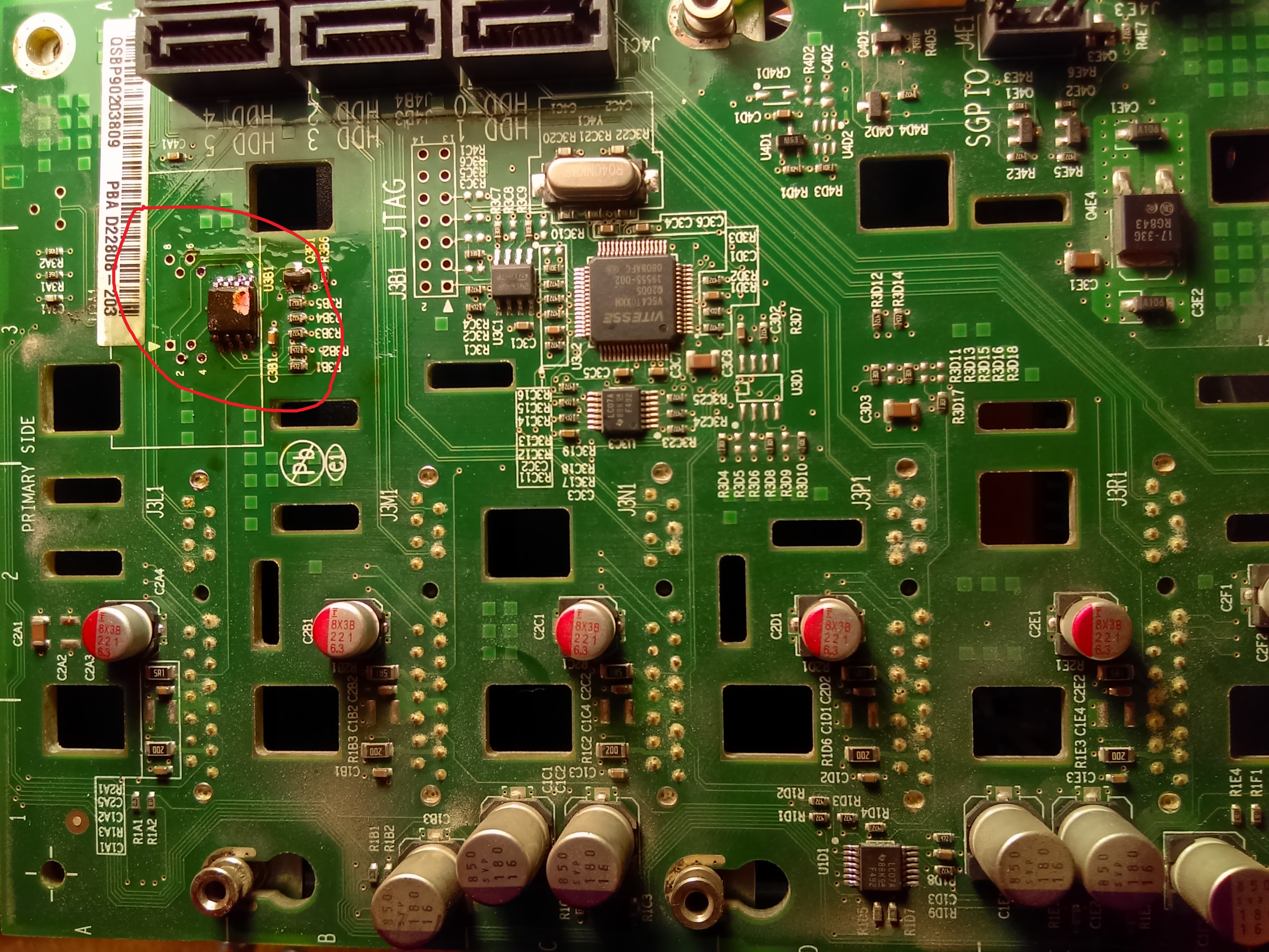
About the SPI chip here it's a picture of the backplane PCB and the SPI in the red circle
You have to desolder it with a electronics heat gun, put it in a programmer and load the bin file or the bin resulted from the hex file supplied by Intel. It's not very complicated, but you have to be careful not to overheat the chip, clean the soldering pads, use good flux and so on.
So, if you see version of the HSC 0.00 you're in trouble
Hope all this adventure of mine will help someone else someday.
Alex.
- Subscribe to RSS Feed
- Mark Topic as New
- Mark Topic as Read
- Float this Topic for Current User
- Bookmark
- Subscribe
- Printer Friendly Page