- Mark as New
- Bookmark
- Subscribe
- Mute
- Subscribe to RSS Feed
- Permalink
- Report Inappropriate Content
Hello everyone,
I have a SV7-2186 server with a S5500WBV motherboard and a Xeon processor.
Its power supply is TDPS-600EB from DELTA.
I am planning to develope a software checking the power consumption of a server.
According to some documents, the power consumption can be checked through PSMI interface.
Thus, I've tried to get the information by using ipmitool which can read FRU data from a power supply.
But, the fru command of ipmitool on my server only shows the FRU data for a motherboard.
I want to know how to get the power consumption information of a server by using IPMItool.
Waiting for your reply and guidance.
Thanks.
Link Copied
- Mark as New
- Bookmark
- Subscribe
- Mute
- Subscribe to RSS Feed
- Permalink
- Report Inappropriate Content
If the power supply supports the required PMbus commands the Intel Active System Console software will display your power (and a bunch of other stuff)
(I don't know if this PS does or not.)
The AUX Power connector (J9D1 (1x7 header) needs to be connect to the SMBUS, but make sure you do not connect the voltage sense line (pin 5) on the Aux power header. Your board is 12v sense and this power supply lloks like a stanard SSI 3.3v.sense
Pins 1,2,4, are used for SMBUS. pins 6,7 are standba power and power on.
ipmitool sensors
will display all the sensor configured in the SDR files (assuming you loaded the SDR's for 'PS1 Power In')
You can also poll the device using IPMITOOL RAW commands. (THESE ARE DANGERIOUS!!! They directly read or write device memory space and if used incorrectly can brick your system. Use at your own risk. No typo's)
A few basic commands to read support PMbus options are:
For the system management software to see the power supply these 2 are required
- PMBUS_REV = ipmitool raw 0x06 0x52 0x09 0xb0 0x01 0x98
Should return 11 ( or a string of numbers one of which is 11) This test is to confirm you are communcation with a PMBus power supply of the correct revision.
- Capabilities = ipmitool raw 0x06 0x52 0x09 0xb0 0x01 0x19
Should return greater than 80h
To read power in
- Quary = ipmitool raw 0x06 0x52 0x0f 0xb0 0x03 0x1a 0x01 0x96
- To tell you what data format the next command will be in (Liniear or direct)
- To tell you what data format the next command will be in (Liniear or direct)
- READ PIN = ipmitool raw 0x06 0x52 0x0f 0xb0 0x02 0x96
The PMbus specification goes in to the format of the returned values.
- Mark as New
- Bookmark
- Subscribe
- Mute
- Subscribe to RSS Feed
- Permalink
- Report Inappropriate Content
I just saw a posting on Sourceforge that looks the same?
If you are using a SR1690WBR the board in it would be a S5500WBR (Standard SSI voltages. Not 12v)
If you have a SR1695WBR the board would be S5500WBVR (12v power )
I am going to guess you have an S1690WBR?
See http://www.intel.com/support/motherboards/server/sb/CS-031278.htm http://www.intel.com/support/motherboards/server/sb/CS-031278.htm
If you have a 690pF axial lead capacator insert it in the connector at J9D1 (aux power connector) between pins 2 and 4 then reflash the FRUSDR and the PS should be seen.
- Mark as New
- Bookmark
- Subscribe
- Mute
- Subscribe to RSS Feed
- Permalink
- Report Inappropriate Content
Yes, the posting on Sourceforge is the same.
My server is SR1690WBR with S5500WB (written on the motherboard, I cannot assure that it is S5500WBR)
I have additional questions.
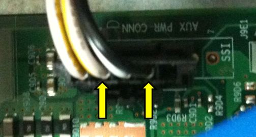
Position of pin2 2 and 4 of J9D1 is here?
Then, all I have to do are
- removing the aux power cable
- connecting the pins once by using 690pF axial lead capacitor during supplying standby power?
Before to do these, I have to buy the capacitor.
I hope to get the capacitor as soon as possible.
Thank you for your valuable information.
Best regards,
Sang Hoon Lee
- Mark as New
- Bookmark
- Subscribe
- Mute
- Subscribe to RSS Feed
- Permalink
- Report Inappropriate Content
Yes, those are the leads & connector.
You do not need to remove the connector, just push the capacitor leads in between the wire and the wire housing right were your arrows are shown and leave then capacitor in place. (a piece of tape around the capacitor the wires is good idea also so that it does not fall out some day and end up on the mother board.) You can solder the leads, but I have found they will stay in place just pushing it in.
The cable referred to in the TA is just this. (Only it is much easier and quicker to make your own)
The cap skews the I2C bus timing just enough so that the BMC is able to talk to the power supply used in this chassis.
The ME is able to communicate with the power supply so the Intel Active System console will report power usage and allow you to set Node manager to limit usage providing full functional use. It is only the use of IPMI tools (and software like you are trying to produce) which route through the BMC (not the ME) which are unable to query the power supply. The SR1695WB power supply does not have this issue.
This connector also confirms the board is the S5500WB(R) as the S5500WBV(R) has a 7 pin connector in this location.
The R indicates refresh to support Westmere (56xx) processors. In the case of WB, other than BIOS code loaded at the factory, the R and non R boards are functionally the same. A 56xx processor will not boot on a older board because of the older BIOS does not support it and you can not update the BIOS because the board will not boot.
- Subscribe to RSS Feed
- Mark Topic as New
- Mark Topic as Read
- Float this Topic for Current User
- Bookmark
- Subscribe
- Printer Friendly Page