- Mark as New
- Bookmark
- Subscribe
- Mute
- Subscribe to RSS Feed
- Permalink
- Report Inappropriate Content
Hi Team,
We tried to check the jic file programming setup in Cyclone v gt eval board. For that we have created the system in FPGA design like this:
nios ii reset and exception vector parameter:
firmware code structure we have followed like this:
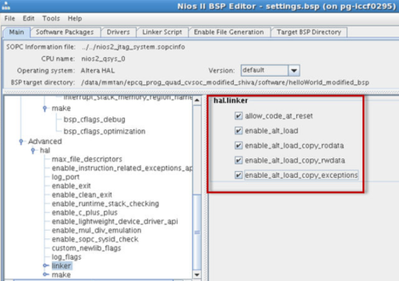
linker script and other parameters in bsp editor:
make target->mem_init gen used to create hex file.
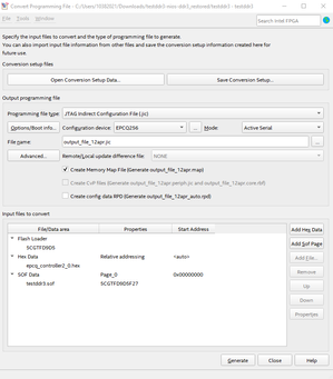
JIC File conversion parameters setup:
with this jic, we have programmed the fpga, Our expected output from this is 3 led should blink( 1 controlled by FPGA DESIGN and other2 controlled by firmware code).
But with jic programming, firmware controlled led is not blinking.
But in .elf file programming, firmware controlled led is blinking.
do we miss anything? Please guide us to resolve this.
- Tags:
- nios_jic_programming
Link Copied
- Mark as New
- Bookmark
- Subscribe
- Mute
- Subscribe to RSS Feed
- Permalink
- Report Inappropriate Content
Hello,
This is to let you know I am investigating your case.
I will get back to you once I have the solution for your issue.
regards,
Farabi
- Mark as New
- Bookmark
- Subscribe
- Mute
- Subscribe to RSS Feed
- Permalink
- Report Inappropriate Content
Hi,
With your Exception Vector (RAM IP settings) set to OCRAM, you need your BSP as follows:
Re-build the BSP and project, and re-generate the new .hex using the "mem_init_generate" tools.
Replace your .hex with this new .hex (with above BSP settings) in Platform Designer and create your new .jic and re-try.
- Mark as New
- Bookmark
- Subscribe
- Mute
- Subscribe to RSS Feed
- Permalink
- Report Inappropriate Content
Hi Eberlazare,
I have tried with the settings you have mentioned in above response, with that also firmware controlled led is not working.
the setting which i have used:
and i have one doubt that two hex files are generated in mem_init folder, i am using epcq hex file only for generating the jic file programming. Is that correct only right?
- Mark as New
- Bookmark
- Subscribe
- Mute
- Subscribe to RSS Feed
- Permalink
- Report Inappropriate Content
Hi,
I think it is because of your Reset Vector offset in your first post, for EPCQ, you need to have offset address for your application as the .jic will also have the .sof at 0x0, so you do not want to overlap it. Anyway, you can find the info here:
https://www.intel.com/content/www/us/en/docs/programmable/683689/current/reset-and-exception-vector-settings.html
You can determine the minimum reset vector offset by using the following equation:
minimum reset vector offset= (.sof image start address + .sof image size) in HEX
You can also try as per the document, set the Reset Vector offset to "0x01E00000".
With that, you need to regenerate the Platform Designer to get the new ".sopcinfo" file and use it to create the new BSP and project.
To confirm you have the Reset Vector offset changed, you can view them when you add in the ".hex" when you try to create the ".jic" file:
- Mark as New
- Bookmark
- Subscribe
- Mute
- Subscribe to RSS Feed
- Permalink
- Report Inappropriate Content
Hi,
We have tried as per the steps you have mentioned in previous response. But relative address is not reflecting in the jic file generation.
reset vector offset is changed in nios ii parameter settings ,
hex data parameter is
we have tried with this , but firmware part is not working. Can you please guide us to resolve this as we have less time to give commitment to customer.
- Mark as New
- Bookmark
- Subscribe
- Mute
- Subscribe to RSS Feed
- Permalink
- Report Inappropriate Content
Hi,
You need to create a new BSP and project in Nios II SBT, with the new .sopcinfo which has the address set.
- Mark as New
- Bookmark
- Subscribe
- Mute
- Subscribe to RSS Feed
- Permalink
- Report Inappropriate Content
Hi,
i have created new bsp and generated hex file. with that also address is not reflecting..
- Mark as New
- Bookmark
- Subscribe
- Mute
- Subscribe to RSS Feed
- Permalink
- Report Inappropriate Content
Hi,
Which Quartus version are you using? Is the Cyclone V GT custom or the dev kit version?
Can you archive the Quartus design to me here? You are using the Hello World template in the Nios II SBT right?
I will help you check and create the .jic on my side.
- Mark as New
- Bookmark
- Subscribe
- Mute
- Subscribe to RSS Feed
- Permalink
- Report Inappropriate Content
Hi,
We are using 22.1 quartus version and currently we are checking the design in starter vino kit eval board.
Yes we are using hello world template only
Can you please check this , because we need to inform customer regarding this.
i have attached the project archive with this . please let me know if any
- Mark as New
- Bookmark
- Subscribe
- Mute
- Subscribe to RSS Feed
- Permalink
- Report Inappropriate Content
Hi,
Please give response for this, our work is blocked with this
- Mark as New
- Bookmark
- Subscribe
- Mute
- Subscribe to RSS Feed
- Permalink
- Report Inappropriate Content
Hello,
Just to let you know that I am checking your case. will get back to you as soon as possible.
regards,
Farabi
- Mark as New
- Bookmark
- Subscribe
- Mute
- Subscribe to RSS Feed
- Permalink
- Report Inappropriate Content
Hello,
I am sorry, I am replacing previous Application Engineer as he is no longer with us.
Can you try to follow this guide: https://www.intel.com/content/dam/support/us/en/programmable/support-resources/fpga-wiki/asset03/nios-ii-processor-booting-from-cfi-flash.pdf
regards,
Farabi
- Mark as New
- Bookmark
- Subscribe
- Mute
- Subscribe to RSS Feed
- Permalink
- Report Inappropriate Content
Hi Farabi,
Ok, we will check and let you know.
i have checked the document which you have shared.
In that configuration, passive parallelx16 is mentioned,
but eval board which we are having is cyclonve v gt eval. In that manual , configuration is active serial mode
Is that ok to use the programming setup in this eval board?
- Mark as New
- Bookmark
- Subscribe
- Mute
- Subscribe to RSS Feed
- Permalink
- Report Inappropriate Content
Hello,
Yes, of course you can use the AS(Active Serial) mode as your configuration.
AS mode is simpler, as it is directly programmed the flash from JTAG via FPGA.
regards,
Farabi
- Mark as New
- Bookmark
- Subscribe
- Mute
- Subscribe to RSS Feed
- Permalink
- Report Inappropriate Content
Hello,
I have provide the answer, I will transfer this case to community now.
If you have new question, please raise another ticket. We will be happy to help.
regards,
Farabi
- Subscribe to RSS Feed
- Mark Topic as New
- Mark Topic as Read
- Float this Topic for Current User
- Bookmark
- Subscribe
- Printer Friendly Page


