- Mark as New
- Bookmark
- Subscribe
- Mute
- Subscribe to RSS Feed
- Permalink
- Report Inappropriate Content
Hello everybody!
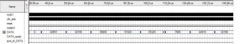
We have chosen the AD7401 Sigma Delta modulator for our project, translated the Verilog code given by the datasheet into VHDL and are now confused about the results of the simulation. We have attached our translated VHDL code plus the datasheet of AD7401. 1) We will give the master clock from the FPGA to the ADC from one of the I/O pins. The clocks don't seem to be synchronized though, there is a 5nsec latch delay. Should that be ok, or do we have to eliminate that delay somehow? 2) We tried to simulate the data flow inputting only ones '1', but result is really not the expected one. (DATA samples should be at the highest level?!) Yes, but what about overflow? The given interface is permitting that, if such a case comes up. Below are some results of a random inputted bit stream and a only '1' bit stream. http://i252.photobucket.com/albums/hh3/unoturbomk2/samples.jpg http://i252.photobucket.com/albums/hh3/unoturbomk2/samples2.jpg *** Is the code correct? *** We'd appreciate any kind of help! Thanks in advance!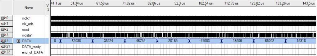
Link Copied
- Mark as New
- Bookmark
- Subscribe
- Mute
- Subscribe to RSS Feed
- Permalink
- Report Inappropriate Content
The original Verilog code is an example of bad coding style, involving word_clk designed as a ripple clock, but it's basically working.
You have confused the code by an adder, that hasn't been there before and apparently act's as a kind of random number generator in your simulation. if mdata1='1' then
ip_data1 <= ip_data1 + '1';
else
ip_data1 <= ip_data1 - '1'; The purpose of this combinational code is to assign 0/+1 respectively -1/+1 to ip_data1, not to sum up anything.
- Mark as New
- Bookmark
- Subscribe
- Mute
- Subscribe to RSS Feed
- Permalink
- Report Inappropriate Content
Can you explain to us how that is expressed in VHDL?
ip_data1 <= 1; Because, for instance, in SBAA094 of ADS1202 it is done the way we did it. DELTA1 <= DELTA1 + 1; Where exactly is our code mistaken, despite the fact that it is bad coding style given by the datasheet itself. Shouldn't vector ip_data1 work as an adder?
- Mark as New
- Bookmark
- Subscribe
- Mute
- Subscribe to RSS Feed
- Permalink
- Report Inappropriate Content
ip_data1 <= conv_std_logic_vector(1,24);
- Mark as New
- Bookmark
- Subscribe
- Mute
- Subscribe to RSS Feed
- Permalink
- Report Inappropriate Content
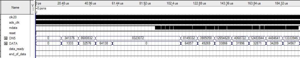
Ok, we tried to merge in some way the code of ADS1202 and AD7401, and we got really great results of the code which came out.
The first figure is with feeding 0's and then random input, and the second one is with 1s first and then random values. http://i252.photobucket.com/albums/hh3/unoturbomk2/2-3.jpg http://i252.photobucket.com/albums/hh3/unoturbomk2/1-5.jpg As you can see the code responses to the simulation quite well, respecting that it actually takes 2 words/samples for the code to respond to sudden changes of input values, due to the 3rd order sinc filter. The code is attached. If someone could confirm that this is correct, we'd appreciate it! Thank you!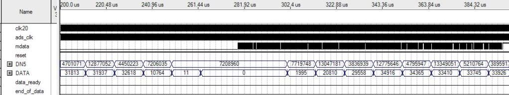
- Mark as New
- Bookmark
- Subscribe
- Mute
- Subscribe to RSS Feed
- Permalink
- Report Inappropriate Content
The results are correct, except for the unhandled arithmetic overflow with mdata = '1'. I suggest to consider it in the code.
  if CN5(24) = '1' then
    DATA(15 downto 0) <= (others => '1');
  else
    DATA(15 downto 0) <= CN5(23 downto 8);
  end if;
- Mark as New
- Bookmark
- Subscribe
- Mute
- Subscribe to RSS Feed
- Permalink
- Report Inappropriate Content
FvM thank you we corrected that, although we had tried that out, but in a different way!
I think that now we are done with this part! Thanks again!- Mark as New
- Bookmark
- Subscribe
- Mute
- Subscribe to RSS Feed
- Permalink
- Report Inappropriate Content
In addition, I see a timing violation in my compilation, caused by the previously mentioned ripple clock. Implementing word_clk as a clock enable removes this problem.
- Mark as New
- Bookmark
- Subscribe
- Mute
- Subscribe to RSS Feed
- Permalink
- Report Inappropriate Content
FvM, I tried to implement it as a clock_enable, but results were terrible!
process(clk20,reset)
begin
  if reset = '0' then
    clk_en <= '0';
  elsif clk20'event and clk20 = '0' then
    cnt <= cnt + 1;				-- cnt is a 8-bit vector
    if cnt(7) = '1' then
      clk_en <= NOT(clk_en);
    end if;
  end if;
end process;
After that I used clk_en in combination with the system clock directly in the processes where word_clk used to be. Could you please suggest to me some other way of implementing that?
- Mark as New
- Bookmark
- Subscribe
- Mute
- Subscribe to RSS Feed
- Permalink
- Report Inappropriate Content
A clock enable should be active for one clock cycle, e.g.:
process(word_count)
begin
 if word_count = x"ff" then
  word_clk <= '1';
 else
   word_clk <= '0';
 end if;
end process;
and if reset = '0' then
--
elsif clk20'event and clk20 = '1' then
if word_clk = '1' then
DN0 <= CN2;
--
end if;
end if;
- Mark as New
- Bookmark
- Subscribe
- Mute
- Subscribe to RSS Feed
- Permalink
- Report Inappropriate Content
Ok FvM I did that and it works great!
I also did the same thing in the last process, where the DATA assignment is done. I think now it works perfectly, most warnings eliminated, except the pin assignment ones! Thank you!
process(clk20,reset)
begin
  if reset = '0' then
    DATA <= (others => '0');
  elsif clk20'event and clk20 = '1' then
    if word_clk = '1' then
      if CN5(24) = '1' then
        DATA(15 downto 0) <= (others => '1');
      else
        DATA(15 downto 0) <= CN5(23 downto 8);
      end if;
    end if;
  end if;
end process;
- Mark as New
- Bookmark
- Subscribe
- Mute
- Subscribe to RSS Feed
- Permalink
- Report Inappropriate Content
FvM,
I was searching for a solution for the clock-output issue we have, and I ended up with PLLs. I read in Cyclone Handbook about how to handle PLL features in Cyclone FPGAs, but I unfortunately found out that the 100-pin EP1C3 device used in PLUTO-II board does not support external clock output. Could you come up with any other (perhaps tricky) solution about how we could drive the ADC from the FPGA, providing it the external 20MHz clock we feed to the board from the dedicated clock input pin? I think we can output the clock from any I/O of the board to the ADC without PLL, but there will be a sync issue of the system clock and the clock feeding into the ADC, am I right? Thank you for your help!- Mark as New
- Bookmark
- Subscribe
- Mute
- Subscribe to RSS Feed
- Permalink
- Report Inappropriate Content
I won't expect any clock output issues with your rather slow clock. What do you mean?
- Mark as New
- Bookmark
- Subscribe
- Mute
- Subscribe to RSS Feed
- Permalink
- Report Inappropriate Content
I mean that the filter/decimation operations will be working with system clock, but data will arrive from the ADC on every falling edge of the clock we output from the FPGA, which has a ~5nsec delay. Could we maybe pass the clock through some delay before outputting it to the ADC so that the 2 clocks are identical? (Tried some NOTs, but unfortunately..)
Something else, what about initialization at system-boot? Do the signals and I/Os need something like an internal reset at the start?- Mark as New
- Bookmark
- Subscribe
- Mute
- Subscribe to RSS Feed
- Permalink
- Report Inappropriate Content
If you specify the timing correctly, Quartus timing analysis will care for it. 5 ns output delay is only part of the involved delay, the ADC has most likely more delay. The problem is common to interfacing external devices.
If you don't need correct measrements from the start, you don't need a reset with your design, I think. You have to check, if it has illegal states, that may cause a dead-lock.- Mark as New
- Bookmark
- Subscribe
- Mute
- Subscribe to RSS Feed
- Permalink
- Report Inappropriate Content
What do you mean by "specifying the timing correctly"?
I understand that the delay will be obviously more than 5ns, and that this is a common problem in interfacing external devices such as an ADC in our case. But unfortunately I really got confused with this, again... Regarding the datasheet, it is mentioned that data is valid during the rising edge of MCLKIN, and max data access time is 25ns (after rising edge). At the point of introducing the recommended filter+decimation code, it is mentioned that data is read on the falling edge. Also, at the interface of the code, mdata is not driven by the system clock, but by itself (sensitivity list, only when mdata changes value ?!). In our code we drive mdata with clk20 at the rising edge. Outputting the 20 MHz clock towards the ADC, concerning 5ns++ (???) delay, and doing the operations of interfacing/filter/decimation with system clock, how can we be sure that we will achieve correct data receiving - synchronization?ads_clk <= clk20; I'm really confused, sorry. I agree that it is not necessary in our application to get correct values/samples from "system-boot" - in worst case scenario there will be only 3-4 distorted samples. I closed every 'IF' block in our code with "else... NULL" operations, so this should be enough to avoid dead-lock. Also, we are going to implement a asynchronous hard-reset pushbutton. Just because of curiosity, would it be difficult to implement an initialization? Thank you so much!
- Mark as New
- Bookmark
- Subscribe
- Mute
- Subscribe to RSS Feed
- Permalink
- Report Inappropriate Content
If a design involves a risk of deadlock condition, they are not avoided by adding functionless code, e.g. "others" in a case construct. The compiler is smart enough to remove it. A deadlock can e.g. occur with illegal states of a state machine, it can be triggered by an incorrect reset or a timing violation of the system clock or an asynchronous input signal. But your design has no stae machines, only binary counters without a risk of deadlock.
Regarding timing of ads_clock and mdata in your design. I see mainly two options: - specify exact timing constraints for the external signals with Time Quest timing analyzer - perform a hand calculation of the expectable mdata timing related to your system clock (clk20) and check if it can be safely received. If not, invert the output clock. Other options are e.g.to generate phase shifted ads_clock through a PLL and send it through general I/O pins. But I think, it's not reasonable for a slow 20 MHz clock.- Mark as New
- Bookmark
- Subscribe
- Mute
- Subscribe to RSS Feed
- Permalink
- Report Inappropriate Content
FvM thank you very much, I'll check out these issues.
- Mark as New
- Bookmark
- Subscribe
- Mute
- Subscribe to RSS Feed
- Permalink
- Report Inappropriate Content
Sir, Hello!
I used the code you write to debug to the actual circuit not simulation, and found it cannot produce word_clk clock signal, so I have written in verilog a divider circuit, to produce mclk and word_clk signal, and made ​​some changes to your program (Delete word_clk produce circuit ), and then debug, I find the result of the conversion are all 0 (DATA [15 .. 0]).After all, it cannot work in actual circuit.I don't know why,Could you tell me?Have you ever used the AD7401 to apply a actual project such as a sampling circuit of voltage? The following is a modified program of you: library IEEE; use IEEE.std_logic_1164.all; use IEEE.std_logic_unsigned.all; entity AD7401decimationfilter is port(reset, mdata, clk20,word_clk: in std_logic; DATA : out std_logic_vector(15 downto 0); ads_clk : out std_logic); end AD7401decimationfilter; architecture RTL of AD7401decimationfilter is signal CN2_D2,DN1_D,DN2_D,DN1,DN2,DN3 : std_logic_vector(24 downto 0); signal CN1, CN2 : std_logic_vector(24 downto 0); signal delta : std_logic_vector(24 downto 0); --signal word_count : std_logic_vector(7 downto 0); --signal word_clk : std_logic; begin ads_clk <= clk20; p11:process(clk20, reset) begin if reset = '0' then delta <= (others => '0'); elsif clk20'event and clk20 = '1' then -- if mdata = '1' then delta <= delta + 1;--mdata; --end if; end if; end process p11; p12:process(reset, clk20) begin if reset = '0' then CN1 <= (others => '0'); CN2 <= (others => '0'); elsif clk20'event and clk20 = '1' then CN1 <= CN1 + delta ; CN2 <= CN2 + CN1; end if; end process p12; --DECIMATION STAGE (MCLKIN/WORD_CLK) --process(clk20,reset) --begin -- if reset ='0' then -- word_count <= "00000000";--(others => '0'); -- elsif clk20'event and clk20 = '0' then -- if word_count="11111111" then -- word_count<="00000001"; -- else word_count <= word_count + 1; -- word_count is an 8 bit reg for decimation 2^8= 256 -- end if; -- end if; --end process; --process(word_count,reset) --begin --if reset = '0' then -- word_clk <= '0'; -- oe<='0'; --else -- word_clk <= word_count(7); -- oe<=word_count(7); --end if; --end process; p13:process(reset, word_clk) begin if reset = '0' then CN2_D2 <= (others => '0'); DN1_D <= (others => '0'); DN2_D <= (others => '0'); DN1 <= (others => '0'); DN2 <= (others => '0'); DN3 <= (others => '0'); elsif word_clk'event and word_clk = '1' then DN1 <= CN2 - CN2_D2; DN2 <= DN1 - DN1_D; DN3 <= DN2 - DN2_D; CN2_D2 <= CN2; DN1_D <= DN1; DN2_D <= DN2; end if; end process p13; --p14:process(word_clk,reset) --begin -- if reset = '0' then -- DATA <= (others => '0'); -- elsif word_clk'event and word_clk = '1' then -- DATA(15 downto 0) <= DN3(23 downto 8); -- extracting the Most Significant Bits MSB -- end if; --end process p14; process(clk20,reset) begin if reset = '0' then DATA <= (others => '0'); elsif clk20'event and clk20 = '1' then if word_clk = '1' then if DN3(24) = '1' then DATA(15 downto 0) <= (others => '1'); else DATA(15 downto 0) <= DN3(23 downto 8); end if; end if; end if; end process; end RTL; *i wrote it myself sub-frequency signal procedure as follows: module dividefrequency(sysclk,reset,mclk1,mclk2,word_clk); input sysclk; input reset; output mclk1; output mclk2; output word_clk; wire sysclk; wire reset; reg mclk1; wire mclk2; reg word_clk; reg [31:0] div_count; reg [7:0] word_count; integer location; integer info_file; //wire [7:0] dec_rate; //parameter rate=256;//280wen,256(12M);//70->1/2 i2c//116->1.4*16; //parameter h_rate=64; //assign dec_rate = 256 - rate;//ini value assign mclk2=mclk1; /* initial begin end */ /*divide sysclk 50MHZ to 6.25MHZ*/ always @(posedge reset or negedge sysclk) if(reset) begin div_count<=0; end else begin div_count<=div_count+1; if(div_count==8) div_count<=1'b1; end always @(div_count,mclk1)//mclk begin if(div_count<=4) mclk1<=1; else if(div_count<=8) mclk1<=0; end always @ (negedge mclk1 or posedge reset) begin if (reset) word_count <= 0; else if (word_count == 8'hFF) word_count <=1;// dec_rate+1; else word_count <= word_count + 1; end /* always @ (word_count) word_clk <= word_count[8]; */ always @ (word_count) begin if(word_count<=64)//64) word_clk<=1; else if(word_count<=8'hff)//255) word_clk<=0; end endmodule sysclk is 50mhz,which is divided to 6.25mhz as mclk and 24.41khz as word_clk.- Mark as New
- Bookmark
- Subscribe
- Mute
- Subscribe to RSS Feed
- Permalink
- Report Inappropriate Content
Hi,
sorry but currently I have no time to look into your issue. I have attached our filter block, which had worked for us (in a real implementation). It contains the part of code that you need. Please disregard the last section tagged as "RAM Writing Process" and its associated signals, and adjust "DATA Assignment Process" to your needs. Hope it helps! BR, David- Mark as New
- Bookmark
- Subscribe
- Mute
- Subscribe to RSS Feed
- Permalink
- Report Inappropriate Content
Thank you first. @dfuschelberger
- Subscribe to RSS Feed
- Mark Topic as New
- Mark Topic as Read
- Float this Topic for Current User
- Bookmark
- Subscribe
- Printer Friendly Page