- Mark as New
- Bookmark
- Subscribe
- Mute
- Subscribe to RSS Feed
- Permalink
- Report Inappropriate Content
Hi all,
I have read the handbook for MAX V and have written the verilog code following the timings in the handbook. The mode of SPI is set to mode 0 and the host samples the data on the rising edge and changes the data on the falling edge. Unfortunately, while looking at the waveforms on the SPI pins using a logic analyzer, I noticed that the UFM is not responding to the currently issued command via the SO pin. I followed the handbook's instructions and enabled the oscena pin. Also, the SPI has a CLK frequency of 12.5M, so I wonder if this is caused by the CLK frequency being too high. I would also like to ask what additional verilog files I need to add to the project if I want to emulate ufm in Modelsim, similar to how I need to add alter_mf.v when emulating the RAM in the IP core.
- Tags:
- MAX V UFM
Link Copied
- Mark as New
- Bookmark
- Subscribe
- Mute
- Subscribe to RSS Feed
- Permalink
- Report Inappropriate Content
Have you tried to low the frequency and check whether it becomes better? BTW, could you please show some picture of your test results to help better understand what happened.
- Mark as New
- Bookmark
- Subscribe
- Mute
- Subscribe to RSS Feed
- Permalink
- Report Inappropriate Content
Hi TingJiangT,
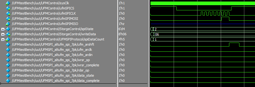
I lowered the SPICLK frequency to 6.25MHz as per the handbook's clocking requirements, but I still don't see a waveform change on the SO pins. Figure (1) shows the WREN state mentioned in the handbook, which has an Opcode of 0x06. Figure (2) shows the waveform of writing 0x0203 into address 0x0001 of the UFM. Figure (3) shows the waveform of reading data from the address 0x0001 of UFM. After giving 16 as the address, two consecutive 0xff are sent to read the data and it is found that there is no change in the waveform of SO pin and it always remains as z state. So, can you provide some flow of writing data from UFM like first to xx, then xx and finally xx.
(1)
(2)
(3)
- Mark as New
- Bookmark
- Subscribe
- Mute
- Subscribe to RSS Feed
- Permalink
- Report Inappropriate Content
Hi,
I had done testing with MAX V megafunction ALTUFM_SPI and can get the proper result check screenshot below:
The simulation options osc frequency only has two which are 5.56Mhz and 3.33Mhz check screenshot below. May be can try with these two osc frequency for sck.
One more thing is the SO only will have value when read operation is performed if check this document https://cdrdv2-public.intel.com/654256/mv51007.pdf page 26 onwards.
Seems like for your case, your ufmSPIMOSI is using extra one ufmSPICLK if compared with mine and manual example waveform.
Also, try to longer your simulation time.
Thanks,
Regards,
Sheng
- Mark as New
- Bookmark
- Subscribe
- Mute
- Subscribe to RSS Feed
- Permalink
- Report Inappropriate Content
Hi there. If you have a new question, Please login to ‘https://supporttickets.intel.com’, view details of the desire request, and post a feed/response within the next 15 days to allow me to continue to support you. After 15 days, this thread will be transitioned to community support. The community users will be able to help you on your follow-up questions.
- Subscribe to RSS Feed
- Mark Topic as New
- Mark Topic as Read
- Float this Topic for Current User
- Bookmark
- Subscribe
- Printer Friendly Page


