- Mark as New
- Bookmark
- Subscribe
- Mute
- Subscribe to RSS Feed
- Permalink
- Report Inappropriate Content
Hi all, I am attempting to interface an ultrasonic range sensor with the DE2 board through the GPIO expansion header. The device has 4 connections, 5v vcc, ground, trigger, and echo. The 5v and ground have been attached to the appropriate power supply pins as indicated in the manual and I'm trying to connect the trigger and echo to a couple of the other pins - say GPIO[0] AND GPIO[1]. The project at this point is being built from scratch rather than coded in VHDL or Verilog, to our detriment, as we are still barely scratching the surface of using the languages. I have build circuitry that should function properly but I'm hitting a roadblock when it comes to actually getting input and output through the pins for some reason. Right now I have a basic test project trying to resolve the issue - please see attached image.
Problem# 1: With the .qsf file we have at the school the GPIO pin assignments are completely missing! Unless they are renamed something other than what's in the manual. That same .qsf file has been working fine all year. I went to altera support to try downloading a newer version but the link doesn't seem to be working properly in edge browser or firefox. Problem# 2: When I try using the 14 pin general purpose IO connector instead it seems to make the assignments, because at least they exist in the .qsf file, but when I compile and program the board the results are way off base. The pin EX_IO[0] doesn't respond at all to SW[0] being toggled - a voltmeter measures no change between the pin and ground. Then pin EX_IO[1], which was supposed to light up LEDR[0] when a voltage was detected is outputting a steady 3.3v even though assigned as an input pin, and LEDR[0] is lit up constantly. Also, segment 1 of HEX2 display is lit up for no discernible reason. I'm coming to the unfortunate conclusion that I have no idea what I'm doing when it comes to using these IO pins and would greatly appreciate any help for this new user. Please assume I know nothing and point me in the right direction. I'm comfortable with a lot of the concepts of digital logic design and I'm comfortable doing research if maybe someone could help me find the right search terms to use. I've been attempting to research this for two days without any breakthroughs. Thanks in advance for any help. Using: Quartus Prime Lite Windows 10 64 bit DE2 board: EP4CE115F29C7N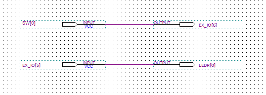
Link Copied
- « Previous
-
- 1
- 2
- Next »
- Mark as New
- Bookmark
- Subscribe
- Mute
- Subscribe to RSS Feed
- Permalink
- Report Inappropriate Content
Okay, I've got everything set with default to ground including the SW, but the problem persists. Do I need to try and ground all the unused pins as well? I don't understand where the voltage could be coming from at this point. If you can think of any other settings or ideas to try please let me know!
- Mark as New
- Bookmark
- Subscribe
- Mute
- Subscribe to RSS Feed
- Permalink
- Report Inappropriate Content
Wanted to post a final update in case someone searches for this issue later. The reason the LED was lit constantly was because of some kind of transient voltage around 0.94V that was present in the input pin and was enough to light the LED and barely enough to tigger a logic high in other things I tested like a multiplexer. The issue, however, went away completely once I read something about unifying the grounds between your input and output devices. I went ahead and hooked up the range sensor via a level shifter (since it runs on 5v logic) and once everything was tied together and grounded the problem went away completely. Hope this helps some poor engineering student in the future.
I'd like to give a special thanks to everyone who helped me resolve this issue. I learned a lot from this experience and look forward to continuing my FPGA education. Without this forum I don't know if I ever would have figured it out alone.- Mark as New
- Bookmark
- Subscribe
- Mute
- Subscribe to RSS Feed
- Permalink
- Report Inappropriate Content
I feel like things are getting closer, thanks so much for all the help. I'll try that other QSF file that was posted as well.
- Subscribe to RSS Feed
- Mark Topic as New
- Mark Topic as Read
- Float this Topic for Current User
- Bookmark
- Subscribe
- Printer Friendly Page
- « Previous
-
- 1
- 2
- Next »