- Mark as New
- Bookmark
- Subscribe
- Mute
- Subscribe to RSS Feed
- Permalink
- Report Inappropriate Content
I currently use the tiny bit of memory on the FPGA for a computer vision project but it's way too limited. I have a stand-alone SDRAM controller from Altera (partially pasted below) but I need one more layer above that which implements this controller as a 2-port RAM entity. It seems like overkill to use QSYS with NiosII though, plus I'm not very familiar with it. What's resource will help me implement this controller as a 2-port RAM entity in the simplest way possible?
entity sdr_sdram is
    generic(
        ASIZE     : integer := 23;
        DSIZE     : integer := 32;
        ROWSIZE   : integer := 12;
        COLSIZE   : integer := 9;
        BANKSIZE  : integer := 2;
        ROWSTART  : integer := 9;
        COLSTART  : integer := 0;
        BANKSTART : integer := 20
    );
    port(
        CLK     : in    std_logic;      --System Clock
        RESET_N : in    std_logic;      --System Reset
        ADDR    : in    std_logic_vector(ASIZE - 1 downto 0); --Address for controller requests
        CMD     : in    std_logic_vector(2 downto 0); --Controller command
        CMDACK  : out   std_logic;      --Controller command acknowledgement
        DATAIN  : in    std_logic_vector(DSIZE - 1 downto 0); --Data input
        DATAOUT : out   std_logic_vector(DSIZE - 1 downto 0); --Data output
        DM      : in    std_logic_vector(DSIZE / 8 - 1 downto 0); --Data mask input
        SA      : out   std_logic_vector(11 downto 0); --SDRAM address output
        BA      : out   std_logic_vector(1 downto 0); --SDRAM bank address
        CS_N    : out   std_logic_vector(1 downto 0); --SDRAM Chip Selects
        CKE     : out   std_logic;      --SDRAM clock enable
        RAS_N   : out   std_logic;      --SDRAM Row address Strobe
        CAS_N   : out   std_logic;      --SDRAM Column address Strobe
        WE_N    : out   std_logic;      --SDRAM write enable
        DQ      : inout std_logic_vector(DSIZE - 1 downto 0); --SDRAM data bus
        DQM     : out   std_logic_vector(DSIZE / 8 - 1 downto 0) --SDRAM data mask lines
    );
end sdr_sdram;
I need a wrapper so that this SDRAM controller is implemented like this: Inst_frame_buffer : entity work.sdram_wrapper_frame_buffer PORT MAP(
rdaddress => rdaddress, -- IN std_logic_vector(18 downto 0);
rdclock => clk_vga, -- IN std_logic;
q => rddata, -- OUT std_logic_vector(11 downto 0)
wrclock => camera_pclk, -- IN std_logic;
wraddress => wraddress, -- IN std_logic_vector(18 downto 0);
data => wrdata, -- IN std_logic_vector(11 downto 0);
wren => wren -- IN std_logic;
);
Link Copied
- « Previous
- Next »
- Mark as New
- Bookmark
- Subscribe
- Mute
- Subscribe to RSS Feed
- Permalink
- Report Inappropriate Content
--- Quote Start --- I have Quartus 13.1 since it is the last version that supports the Cyclone III used in the DE0. --- Quote End --- In Qsys, if you select Generate->Example Designs, the submenu is empty, so I guess it is not supported. For DDR you can generate an example design. You'll have to look on ISSI's web site or Micron's web site for a suitable SDRAM model. I'd recommend reading the Altera SDRAM controller user guide and seeing if they have an example, but Altera's new web site is terrible, so I doubt you can find anything ... Cheers, Dave
- Mark as New
- Bookmark
- Subscribe
- Mute
- Subscribe to RSS Feed
- Permalink
- Report Inappropriate Content
1. download the vendor model I found them here (http://www.issi.com/us/product-dram-sdr.shtml) but there are two choices: ibis-tsop (http://www.issi.com/ww/models/ibis/42s16400j_t.ibs), ibis-bga (http://www.issi.com/ww/models/ibis/42s16400j_b.ibs) any idea which one I should use? TSOP
2. install the model in the system_sim directory.Do you know where this folder is? I haven't been able to find it.3. add the vendor file to the list of files passed to 'vcom' in setup_sim.do.Do you know where setup_sim.do is? 4. instantiate sdram simulation models and wire them to testbench signals. Is this (A) the same as what I would already have for the SDRAM instance, or is it ( B ) a different entity that takes the place of my SDRAM instance with different port signal names?
- Mark as New
- Bookmark
- Subscribe
- Mute
- Subscribe to RSS Feed
- Permalink
- Report Inappropriate Content
Take a look at this zip file. Unzip it. Start Modelsim. Change directory to the zip file, and then type 'source sim.tcl' (without the single quotes).
That'll run a dead simple test of a Micron model that I just happened to have lying around in my source tree. You can figure out how to do the same for your SDRAM model, and then once you understand how the model works, you can add the Altera SDRAM controller and simulate that. Cheers, Dave- Mark as New
- Bookmark
- Subscribe
- Mute
- Subscribe to RSS Feed
- Permalink
- Report Inappropriate Content
I ran the tcl script in modelsim, saw the waveform, and understand what is being shown. I looked through the vhd files also included. I see that a test bench was either created by hand or generated. That doesn't really answer my immediate questions though.
I have a 42s16400j_t.ibs file and an existing test bench. I'm looking for the specific, handful of steps that integrate this simulation model file with modelsim, and then the small corrections that need to be made to the SDRAM instance in my existing test bench (which was generated by QSYS and then modified by me). It shouldn't involve writing the simulation for the entire SDRAM initialization process or anything like that. Wouldn't there be a few steps involved in importing the 42s16400j_t.ibs file to modelsim, followed by the slight modification of my existing test bench? The warning output in modelsim that I posted earlier seems to imply that..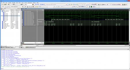
- Mark as New
- Bookmark
- Subscribe
- Mute
- Subscribe to RSS Feed
- Permalink
- Report Inappropriate Content
--- Quote Start --- I see that a test bench was either created by hand --- Quote End --- Pretty much all testbenches are created by hand, since your tests are project specific :) --- Quote Start --- I have a 42s16400j_t.ibs file and an existing test bench --- Quote End --- What is an .ibs file? Sounds like an IBIS file to me, and you would not use that as an SDRAM model. Are you sure you've downloaded something that is actually useful??? --- Quote Start --- handful of steps --- Quote End --- 1. Create Qsys system 2. Instantiate Qsys system in your top-level design (assuming the Qsys is not your top-level design) 3. Instantiate your top-level design in your testbench 4. Instantiate the SDRAM model in your testbench 5. Run your simulation --- Quote Start --- It shouldn't involve writing the simulation for the entire SDRAM initialization process or anything like that --- Quote End --- Why? You need to check that the SDRAM is initialized correctly. Most SDRAM models have a faster initialization sequence in simulation. Cheers, Dave
- Mark as New
- Bookmark
- Subscribe
- Mute
- Subscribe to RSS Feed
- Permalink
- Report Inappropriate Content
Yea, the file I have is not for this type of simulation. I need a bus functional model instead. I was reading up on that and it seems like QSYS generates those alreeady..
It seems like the 'Generate Testbench System' feature of QSYS is what I should have been focusing on using. Apparently there is such a thing as mpf files which are modelsim project files and QSYS generates them for you. Not only that, it generates the simulation file too. So in a few clicks you can go from an empty modelsim window to looking at the simulation of your QSYS system before having written any test benches. Of course you would still make changes to the testbench it generates but it sure seems to automate several of the tedious steps. If you already knew about all of that then the big question is why wasn't that the focus instead of trying to do it manually? Of course QSYS threw some errors while it was generating the test bench which may have a lot to do with why I'm seeing a lot of uninitialized waveforms but those errors may be trivial to fix..- Mark as New
- Bookmark
- Subscribe
- Mute
- Subscribe to RSS Feed
- Permalink
- Report Inappropriate Content
--- Quote Start --- I need a bus functional model instead. --- Quote End --- Generally its just called an SDRAM model. A BFM is the term used for the simulation of the Avalon-MM master/slave and the AXI interfaces. --- Quote Start --- If you already knew about all of that then the big question is why wasn't that the focus instead of trying to do it manually? --- Quote End --- Did you not read Post# 43? What you describe works perfectly well for DDR, but it appears that it does not work for SDRAM. Basically Altera did not add that feature for SDRAM. You could always file a Service Request and ask them how they expect you to simulate their SDRAM Controller. Perhaps they'll have a recommendation. Either way, the method I have told you to create a testbench with an SDRAM model works perfectly fine. The hard part seems to be finding a VHDL/Verilog model! Cheers, Dave
- Subscribe to RSS Feed
- Mark Topic as New
- Mark Topic as Read
- Float this Topic for Current User
- Bookmark
- Subscribe
- Printer Friendly Page
- « Previous
- Next »