- Mark as New
- Bookmark
- Subscribe
- Mute
- Subscribe to RSS Feed
- Permalink
- Report Inappropriate Content
Dear community,
on the C5SX development kit I would like to test a 1 GB Ethernet connection with the Triple Speed Ethernet IP core.
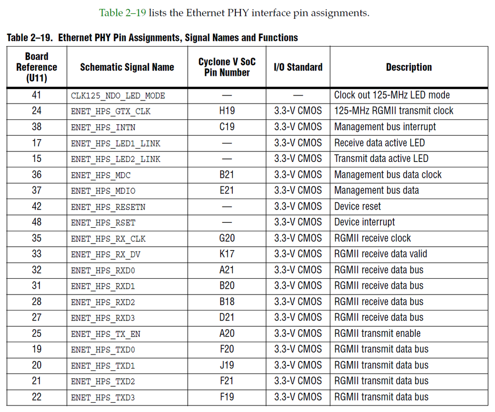
The core is configured with an RGMII output to the Micrel KSZ9021RN PHY. I have found the corresponding pins in the dev kit documentation - the schematic shows the same pins - so I think the pins are correct.
But the Fitter insists that the pins are wrong. For every RGMII pin I try to allocate I get the following errors:
Fitter Errors:
Error (14566): The Fitter cannot place 2 periphery component(s) due to conflicts with existing constraints ...
Error (175020): The Fitter cannot place logic pin in region (68, 81) to (68, 81), to which it is constrained, because there are no valid locations in the region for logic of this type.
Error (184016) There are not enough single-ended output pin locations available
What does this mean?
Thank you
Best regards
-------------
Excerpt from the top.vhd-file
FPGA RGMII Ports (bold = assigned pins)
eth0_mac_rx_clk : out std_logic; -- RX Clock (G20)
eth0_mac_tx_clk : out std_logic ; -- TX Clock 125MHz (H19)
eth0_rgmii_in : in std_logic_vector(3 downto 0) ; -- RX Bus (D21, B18, B20, A21)
eth0_rx_ctrl : in std_logic; -- RX data valid (K17)
eth0_rgmii_out : out std_logic_vector(3 downto 0); -- TX Bus (F19, F21, J19, F20)
eth0_tx_ctrl : out std_logic -- TX data valid (A20)
.qsf file
set_location_assignment PIN_D21 -to eth0_rgmii_in[3]
set_location_assignment PIN_B18 -to eth0_rgmii_in[2]
set_location_assignment PIN_B20 -to eth0_rgmii_in[1]
set_location_assignment PIN_A21 -to eth0_rgmii_in[0]
set_location_assignment PIN_F19 -to eth0_rgmii_out[3]
set_location_assignment PIN_F21 -to eth0_rgmii_out[2]
set_location_assignment PIN_J19 -to eth0_rgmii_out[1]
set_location_assignment PIN_F20 -to eth0_rgmii_out[0]
set_location_assignment PIN_G20 -to eth0_mac_rx_clk
set_location_assignment PIN_K17 -to eth0_rx_ctrl
set_location_assignment PIN_H19 -to eth0_mac_tx_clk
set_location_assignment PIN_A20 -to eth0_tx_ctrl
For all the above pins. all pins I set:
set_instance_assignment -name IO_STANDARD "3.3-V LVCMOS" -to <pin name>
Fig. Doku pins
- Mark as New
- Bookmark
- Subscribe
- Mute
- Subscribe to RSS Feed
- Permalink
- Report Inappropriate Content
I now think the problem with the pins on the CVSX SoC is because the RGMII pins are in the HPS (Hardware Processor System) part of the FPGA, which cannot be directly connected by FPGA vhdl code.
Link Copied
- Mark as New
- Bookmark
- Subscribe
- Mute
- Subscribe to RSS Feed
- Permalink
- Report Inappropriate Content
I now think the problem with the pins on the CVSX SoC is because the RGMII pins are in the HPS (Hardware Processor System) part of the FPGA, which cannot be directly connected by FPGA vhdl code.
- Mark as New
- Bookmark
- Subscribe
- Mute
- Subscribe to RSS Feed
- Permalink
- Report Inappropriate Content
Hi,
I’m glad that your question has been addressed, I now transition this thread to community support.
If you have a new question, feel free to open a new thread to get the support from Intel experts.
Otherwise, the community users will continue to help you on this thread.
Thank you.
- Subscribe to RSS Feed
- Mark Topic as New
- Mark Topic as Read
- Float this Topic for Current User
- Bookmark
- Subscribe
- Printer Friendly Page
