- Mark as New
- Bookmark
- Subscribe
- Mute
- Subscribe to RSS Feed
- Permalink
- Report Inappropriate Content
I have had a lot of fun and some heart ache playing with the MKL Library and the PARDISO solver.
The PARDISO solver is very fast. The problem I am solving is the hydraulic network problem, in this case using the Gradient Method. The PARDISO solver gives a much better first estimate of the solution vector, which can be measured using the error on the sum of the hydraulic heads. It's first pass gives a 4 fold better estimate than the other solvers (all that I have tried).
But the solver then converges very slowly to the "best estimate" of the answer, taking 8000 iterations to do what the others do in 20. So the fact that the iterations are fast, is lost in the slow convergence.
I have played with passing the A array into the PARDISO solver in different formats, both the sparse and the dense matrix, it makes no difference. Rum really. I look step by step at the solution vector, and it is a long way from the other inversion solution vector even on the first iteration for the fully dense solvers.
Interestingly if I run as a PHASE 33 - I get errors, but it works, if I use 13 - it also works slowly, but I do not get the errors.
It does solve, but it is not faster in the end than the other solvers, interesting really.
Question: Should I try another MKL solver?
JMN
Link Copied
- Mark as New
- Bookmark
- Subscribe
- Mute
- Subscribe to RSS Feed
- Permalink
- Report Inappropriate Content

Here is a modest change that can result in at least a 10 percent speed-up. Instead of calling FindNode often, add two more components, nodeI and nodeJ, to the derived type spipe. Before the "DO i=1, 24" loop, add the following lines to set the values of spipes(:)%nodeI and spipes(:)%nodeJ:
        do i = 1, Npipes
           call FindNode(factors, snodes, Nnodes, spipes(i)%n1, spipes(i)%NodeI)
           call FindNode(factors, snodes, Nnodes, spipes(i)%n2, spipes(i)%NodeJ)
        end do
In all places where you currently call FindNode, replace the paired calls to FindNode as follows:
            do k2 = 1, Npipes
                nodeI = spipes(k2)%nodeI
                nodeJ = spipes(k2)%nodeJ
                ...
In general, moving loop invariants to positions just before or just after the loop is easy to do and worthwhile. For example, in the "Nodes Section" of hsolve(), replace
                    do j1 = 1, Nnodes
                        J(i, j1) = 0
                        J(i, i) = 1
                    end do
with
                    do j1 = 1, Nnodes
                        J(i, j1) = 0
                    end do
                    J(i, i) = 1
he matrix is a bit sensitive to errors in diameter.
Of course! For a given flow, Δp ~ d-5, so sensitivity (to changes in diameter as well as build up of pipe deposits) is a known fact of life.
- Mark as New
- Bookmark
- Subscribe
- Mute
- Subscribe to RSS Feed
- Permalink
- Report Inappropriate Content
Dear medej4:
Thanks. I will make those changes tonight.
As you see in your great picture the bulk of the J matrix is zeros, I was looking at the 2 by 2 matrix element, after thinking about your earlier comments, that is added to the J matrix to make the overall pattern, one element of the 2 by 2 comes from one node and the other from the other node at the end of the pipe, and two non diagonal elements are related to the pipe. One can calculate and then store the values in the node and pipe class and then assemble the PARDISO matrix, will get rid of the J matrix.
So if we have 100000 nodes and 100000 pipes, it merely adds 400000 real(8) to the program whilst taking away a J matrix that would be 10 ^ 10 elements.
Thanks
JMN
- Mark as New
- Bookmark
- Subscribe
- Mute
- Subscribe to RSS Feed
- Permalink
- Report Inappropriate Content
JMN wrote:
...will get rid of the J matrix...
Consider it done! The attached zip file contains a number of modifications to your program, the main changes being:
- A sparse Jacobian is assembled using the COO representation. Since MKL Pardiso and Pardiso-5 accept only CSR matrices, a conversion is done by calling MKL_DCSRCOO.
- The D'Arcy - Weisbach equation is used (along with the Colebrooke-White equation for the friction factor) to compute pipe flows from head losses.
- No iteration acceleration factor is used since it causes divergence. However, convergence is already very good (except at the very beginning, when the guessed flow0 is set to an arbitrary value and convergence takes over ten iterations, two or three iterations are sufficient for each subsequent hourly calculation).
- The PIPE lines in the input data file take the values of (i) wall roughness in metres and (ii) water temperature in deg-C in the last two columns. The kinematic viscosity of the water in each pipe is calculated using the input temperature. I guessed that if you have a network with above-ground and under-ground pipes, it would be nice to take the variations in temperature into account.
On a Linux PC with a C2D-E8400 CPU, running the program on p3dw.in gave me
   Program Execution Time :   0.364 s
   Completed Program Execution

real    0m0.413s
user    0m0.324s
sys     0m0.044s
There are linear equation solvers in IMSL, HSL and NAG that accept sparse matrices in COO format. I have tried MA48, and the results are very good. It may be worth trying sparse banded matrix solvers, as well.
The attached program version should be capable of solving big problems, since it does not use a 2-D array for the Jacobian. To use the program for large problems, change the following line (line-33 of magni.f90 in the Zip file)
INTEGER, PARAMETER :: NPIPESMAX = 269, NNODESMAX = 180, NTANKSMAX = 1, NPUMPSMAX = 1, IDMAX = 500
The program will fail if the network specified has more than one pipe connecting any pair of nodes. Are such networks rare?
- Mark as New
- Bookmark
- Subscribe
- Mute
- Subscribe to RSS Feed
- Permalink
- Report Inappropriate Content
Dear mecej4:
I teach some fairly bright students, I tell them that there is a very small and rare group of people who can solve difficult numerical problems with ease. In my lifetime of teaching about 5000 students in engineering subjects, I have encountered 5 of them. I met the first one at ANU in 1975. There was not a physics problem this guy could not solve. He argued with world class physicists in his freshman class, I was lost in the book.
You appear to fit into that group.
I do not, I accepted that the day I got 22 on the exam the red haired kid (noted above) got 99 on, the class average was 26, the other highest score was 30. A number of the ones who got 30 or less now teach and research physics at real tier one schools.
The program will fail if the network specified has more than one pipe connecting any pair of nodes. Are such networks rare?
This is an interesting topological question, but it cannot occur in the mathematical reality within our system as it should be a network to itself and there must be zero head loss around the network, but it is not a network so it breaches the fundamental mathematics, our math system is more constrained than the real world. A bit like the singularity in structural matrix problems, in reality is unlikely because we never build to the minimums unless we make a mistake. OSHA for instance require four bolts on all columns, when two is the amount required for the math. We design the topology assuming 2 but put in 4.
Streeter and Wylie provide an example of this type of pipe system. in reality it is a special class of pipe that had Q = sum of the pipe Q's. The head loss is equal, one would replace it with an equivalent pipe or you would need to amend the underlying mathematics assumptions for the whole program and no one in their right mind wants that. It is of course one problem where two small reservoirs are built on a hill and connected together, the pipes have the same end node, so one always introduces fake nodes. In the recent Tamworth Model I have been working on the One Tree Hill system represents this problem type, it is actually a difficult problem to allow for junior modellers.
JMN
- Mark as New
- Bookmark
- Subscribe
- Mute
- Subscribe to RSS Feed
- Permalink
- Report Inappropriate Content
Page 1 Wed Oct 22 20:09:44 2014
******************************************************************
* E P A N E T *
* Hydraulic and Water Quality *
* Analysis for Pipe Networks *
* Version 2.00.12 *
******************************************************************
Analysis begun Wed Oct 22 20:09:44 2014
WARNING: Pump WellPump#1 closed because cannot deliver head at 0:06:00 hrs.
WARNING: Pump WellPump#2 closed because cannot deliver head at 0:06:00 hrs.
WARNING: Pump WellPump#3 closed because cannot deliver head at 0:06:00 hrs.
WARNING: Pump WellPump#4 closed because cannot deliver head at 0:06:00 hrs.
WARNING: Pump ResvrPump closed because cannot deliver head at 0:06:00 hrs.
WARNING: Pump ResvrPump closed because cannot deliver head at 2:00:00 hrs.
I used the Cl compiler to create a copy of the epanet exe file. I added a simple timing routine. I then tried the simple models supplied by the EPA and it runs in about a second. (Very small model)
There is a Micropolis Model which has about 1800 nodes, but it reads ok, but I get an interesting set of errors.
The NET format used by EPANET is problematic because it does not put all of the data for one entity on one line, and there is no reason not to and all the reasons in the world to do this, but the simple way around is to create a reader that reads the net files and creates them.
Why change a good system?
your revised program is very fast and compact.
I will now try to create a large model.
JMN
- Mark as New
- Bookmark
- Subscribe
- Mute
- Subscribe to RSS Feed
- Permalink
- Report Inappropriate Content
JMN wrote:
I will now try to create a large model.
I look forward to that. Of the two problems for which you posted data files in WSA format, the first one (FileM.in) has 11 unknowns and 9 non-zero-diagonals in the J matrix. The second (File3.in) has many more unknowns (180), but is degenerate in that it leads to only five non-zero-diagonals.
It would be nice to have a number of large models, some of which are representative of real water distribution systems, and a few that have more rich connectivity (and thus a larger fraction of diagonals that are not zero).
Do you have any references or links to collections of problems?
- Mark as New
- Bookmark
- Subscribe
- Mute
- Subscribe to RSS Feed
- Permalink
- Report Inappropriate Content
- Mark as New
- Bookmark
- Subscribe
- Mute
- Subscribe to RSS Feed
- Permalink
- Report Inappropriate Content
- Mark as New
- Bookmark
- Subscribe
- Mute
- Subscribe to RSS Feed
- Permalink
- Report Inappropriate Content
I have so many problems uploading files that I did it first.
I have to models of about 2000 nodes each, one I have in MAGNI format, but I am still sorting out the pump curves and trying to get some more contour data. The problem with these big real models is that they contain modelling errors, so as you load the data for analysis all the different forms of errors pop up and one needs to trap for them.
The one you raised of the two pipes between the same two nodes is a problem at the reservoirs on One Tree Hill and I spent a few hours looking at the plans and trying to work out how to model it. I think that one needs to model the two tanks as one reservoir in the end. The large pipes connecting the two tanks are merely to assure that they do operate at the same level. In thinking conceptually about the problem however, the issue could be handled by adding a pipe count to the SPIPE class and then adjusting the code for calculating the flow. A classic example would be the six pipes connecting two of the big reservoirs in the Snowy system in Australia.
The problem with real systems is the fear of ISIS and the ilk in the community, so that people are loath to share plans. I was trying to do an update paper on the energy pipelines in the USA. The Feds went ballistic when I asked for the overview plan, interestingly I got it from Dick Cheney's office and then sent it to the Feds, then they went ballistic again. IT was an interesting but brief discussion. Then I published the paper.
There is a Micropolis system developed by a chap at my University, it is attached, the log file is the actual EPANET model, but I cannot upload a net file. Humans however create towns that are regular - look at the bit map, so the math degenerates as you note.
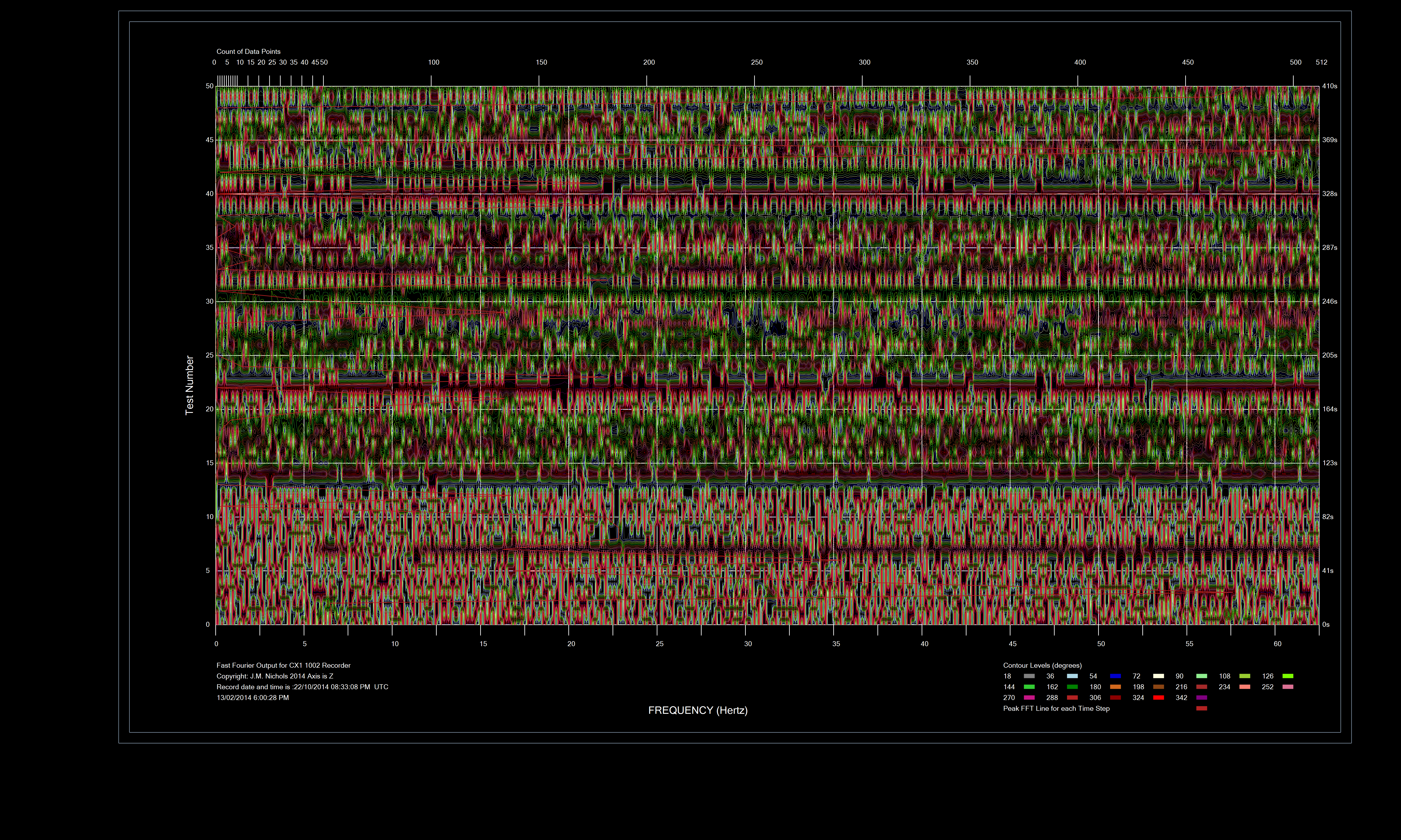
My other problem at the moment is a large proposal for the Europeans on Vibration, we have till the 30th Nov to complete the final proposal, we use a CX1 accelerometer to measure the vibration of bridges and the such. The system does not have a strong software support system yet and we are trying to learn how to interpret the data that comes out. The attached bitmaps show a small load on a bridge at our UNI. The first shows the amplitude of 51 FFT traces of 8 seconds contoured and the second shows the phase angle and the rotation of the phase angle between FFT points. The common assumption in the seismic type models is the phase angle is a random variable (Boore et al from the USGS) but it is not - it rotates at a reasonably fixed rate. The FFT bitmap shows the actual amplitude for the 51 FFT's plotted on one graph.
The analysis looks at the outliers to see if there are changes. We basically have to build and destroy a bridge looking for the changes so it is tedious and expensive in time and writing the code is a bit of an exercise. The CX1 is a USB and Ethernet based device, so it uses the WINUSB driver, the manufacturer uses C# to -- hang on students
- Mark as New
- Bookmark
- Subscribe
- Mute
- Subscribe to RSS Feed
- Permalink
- Report Inappropriate Content
So this is the picture of the Micropolis site.
The CX1 is a lot of fun, but like all new technology it will take a while to sort out. The C# programs to access the machine have made it interesting, I did it in Fortran for a long time and then wanted direct access to the data so I rewrote the code in C#. The big trick was the contouring it really shows up a lot of features you miss in trying to look at 50 FFT plots.
JMN
- Mark as New
- Bookmark
- Subscribe
- Mute
- Subscribe to RSS Feed
- Permalink
- Report Inappropriate Content
It now appears to me that a simple modification to the program will allow treatment of problems in which some node pairs are connected by more than one pipe. The MKL routine mkl_?csrcoo has no allowance for accumulating repeated entries (i.e., more than one triplet {row, col, val} with the same values for row and col. Many library routines (HSL, IMSL, NAG, etc.) that work with COO matrix input allow for repeated entries.
However, we can make up for this deficiency of mkl_?csrcoo by adding just a few lines of code between the calls to mkl_?csrcoo and Pardiso. I made this extension and tried it out on a modified version of the problem in Filem.in. The modification: add a 50 mm pipe between nodes 5 and 6, and another 50 mm pipe between nodes 7 and 8. The results looked reasonable when compared to the old results.
Do you have a WSA input file for a system with such parallel pipes? "One Tree Hill" or "Snowy", perhaps? There is no need to make up equivalent single pipes.
If the EPANET GUI program had a way of exporting the data for a model as a text file, we would be able to modify the output text file to derive a WSA input file. I did not see any provision for doing this, but then I have used the EPANET program only once.
- Mark as New
- Bookmark
- Subscribe
- Mute
- Subscribe to RSS Feed
- Permalink
- Report Inappropriate Content
So I spent the last two days writing a Fortran program to take the EPANET INP (ASCII file) and create a file for our Water Supply Analysis program, at the same time I tired to teach 120 students how to read steel plans. So the code is ruff and ready. I used the MICROPOLIS model from TAMU. It is a rectilinear model, with some of the features you would expect from someone who teaches modelling, but does not look after real models - mainly complicated names.
The node numbering system is VN1 to VN1000 and a group other codes mostly two alphas and then numbers up to 1000. We use numbers only for ease of use and searching, so I took the VN1000 and treated it as abase 27 number and translated it to decimal, used this as on offset storage to temporarily store our index numbers for the nodes and pipes. Works quite nicely except for the odd things like PUMPSTATION.
There are an awful lot of valves in this model, so for the moment I treated them as short open pipes, which in reality they are if they are open and all bar one is open.
The model has problem when it runs, mainly topological correctness, so that it today's task. Code is attached.
The EPANET program is based on a program by George and Liu, Computer Solutions of Large Positive Sparse Definite Systems, which was available through the library - it is so old it is stored an offsite facility. (1981 is not that long ago)
I have been reading the book and it has a lot of good stuff, along the lines of your comments. The reason the large but simple model I made had the layout shown in the MATLAB picture is I numbered all of the nodes 1 to n along a long street, a common practice as you develop models and then started n+1 back at the start of the parallel street and then infilled the cross streets. If you are creating these models using a digital program such as AutoCAD, that is a natural way to do the work for a draughtsperson. The problem is that they create topological errors in the model, leave out pipes, put two nodes really close together so they look one node but are not. The issue at this size is model correctness. The interesting issues of two pipes between nodes can also be a problem. One method this happens is some accidentally creates a duplicate pipe on a layer that is turned off.
So I enclose the code I created - it is not good, but it works for the most part and the model. It is part of MagniSample, the A.IN is the EPANET input file and the B.IN is our format.
JMN
- Mark as New
- Bookmark
- Subscribe
- Mute
- Subscribe to RSS Feed
- Permalink
- Report Inappropriate Content
This is the model as run, I added some tanks to at least get it working, I will go back and try and fix the model.
At least it is not the old days where you had to drive to Sydney to do a run on the mainframe.
This b.in includes the tanks.
The rpt file shows the topological issues.
Dr George, who wrote the book, that Rossman used as the base for the EPANET inversion routines is still at Waterloo University, so I sent him a note.
JMN
- Mark as New
- Bookmark
- Subscribe
- Mute
- Subscribe to RSS Feed
- Permalink
- Report Inappropriate Content
JMN: The data in the file b.in contained in b.zip (#55) has at least this error: Pipe 1415 is supposed to connect Nodes 1443 and 1574, but the earlier part of the file contains node data only up to Node 1573. Is it enough just to provide data for Node 1574?
Pipes 1493 and 1611 connect the same pair of nodes, nos. 1106 and 1107. Is this a mistake, or intentional?
The program needs to be given more data checking capabilities to catch such errors.
Is there a correct version of "a.in", that is, the data for Micropolis, for which EPANET produces plausible results? The file that is provided at the TAMU link (https://ceprofs.tamu.edu/kbrumbelow/Micropolis/EPANet-Micropolis_v1.zip) results in the EPANET report file containing nothing beyond title lines and errors, "Pump xxxxx closed because cannot deliver head at h:mm:ss hrs".
There is a place (http://iridia.ulb.ac.be/~manuel/files/pumps/) where there are EPANET input files that produce plausible report files. Could some of those be converted to WSA input format? Other sample input files that you may have already noted, but I don't know whether it is feasible to convert them:
http://emps.exeter.ac.uk/media/universityofexeter/emps/research/cws/downloads/Richmond_skeleton.inp
http://emps.exeter.ac.uk/media/universityofexeter/emps/research/cws/downloads/Richmond_standard.inp
http://emps.exeter.ac.uk/media/universityofexeter/emps/research/cws/downloads/wolf-initial-fig.inp
- Mark as New
- Bookmark
- Subscribe
- Mute
- Subscribe to RSS Feed
- Permalink
- Report Inappropriate Content
I have a program from many years ago that checks water supply analysis graphs for data correctness, i.e. properly formed and in the correct ranges. I am currently amending it to read the WSA program format, a first pass shows about 200 errors in the TAMU file. I will put it up here as soon as I get it fixed, I am trying to sort out the different errors.
I will look at the other sites and see if these models are better.
JMN
- Mark as New
- Bookmark
- Subscribe
- Mute
- Subscribe to RSS Feed
- Permalink
- Report Inappropriate Content
I got the nodes and the pipes for the English Sample system into the WSA format.
Their numbering is all over the place and they use A B C D E F and O as reservoir nodes. As I translated the system I have renumbered it to a consistent system. I have some errors in my format statements, I need to do these again in places and make them sensible.
But the file reads as input at least. I still have to put in the eight reservoirs. As soon as I do that I will put it up.
No point playing without a full deck.
JMN
- Mark as New
- Bookmark
- Subscribe
- Mute
- Subscribe to RSS Feed
- Permalink
- Report Inappropriate Content
Dear mecej4:
It got quite frustrating for a few days, I have now put in a tolerable level of error checking that for bad errors will stop the execution and for other errors will warn you that something is amiss.
This is not perfect, but it does handle the p3dw file nicely and points out some of the errors in the RICH (Richmond water Supply File). THis file is designed to test systems and it has a lot of interesting features. I can get it running in EPANET, but I would not trust the solution as it has some very weird elements. Without a full plan it is hard to find the errors, so I am going to make one.
I spent quite a deal of time putting errors into the p3dw file and then trapping them. I do not have all of them but I have the worst offenders that I can think off.
I am still working on the zone and adjacency problem, interesting to be sure. I have a separate program that creates the Hardy Cross File type for another program, this has some error checking, but I thought it better to put it into WSA.
Some errors are not errors if you use HW and feet, but we don't so I am sticking to DICL pipe.
I liked your addition of the CW and DW equation.
JMN
- Mark as New
- Bookmark
- Subscribe
- Mute
- Subscribe to RSS Feed
- Permalink
- Report Inappropriate Content
There are a couple of things that appear to be a bit off in the files Final.inp (which appears to be a modified version of http://emps.exeter.ac.uk/media/universityofexeter/emps/research/cws/downloads/Richmond_standard.inp) and Rich.inp, which I assume to be obtained by converting Final.inp to Magni input format.
In Final.inp, nodes 3002 and 3003 have identical coordinates. Node 3003 does not appear in any PIPE section entry. Node 3006 appears in the COORDINATES sections, but is an orphan otherwise. The original Richmond_standard file contains 872 nodes and 949 pipes, whereas Rich.inp contains 871 nodes and 949 pipes.
- Mark as New
- Bookmark
- Subscribe
- Mute
- Subscribe to RSS Feed
- Permalink
- Report Inappropriate Content
There are a couple of things that appear to be a bit off in the files Final.inp (which appears to be a modified version of http://emps.exeter.ac.uk/media/universityofexeter/emps/research/cws/down.) and Rich.inp, which I assume to be obtained by converting Final.inp to Magni input format.
In Final.inp, nodes 3002 and 3003 have identical coordinates. Node 3003 does not appear in any PIPE section entry. Node 3006 appears in the COORDINATES sections, but is an orphan otherwise. The original Richmond_standard file contains 872 nodes and 949 pipes, whereas Rich.inp contains 871 nodes and 949 pipes.
---------------------------------------------------------------------------------------------------------------------------------------------------------------------------------------
I got the Richmond File running in the EPANET program. Node 3003 is not connected to any pipe, so it had to be deleted from the original EPANET model. The model jumps around a bit with the pumps and NRV in the solution. yes, the RICH.INP file is simply a reformatted epanet.inp file for the same model, without the pumps or the Non-return valves. I have to include a non-return valve in our model and also translate the EPA pumps into a form I can use in the WSA program. I still need to include code to check that the nodes in the node section match nodes in the pipe section, I am most of the way there. I am trying to get the code to identify the different zones, automatically - this will make the problem set up easier. The Richmond model shows a reservoir with dual pumps and a NRV, it is an interesting combination that has the two pumps going from one node to another in parallel, similar to the problem you were talking about.
The Richmond model has a complex set of valves and pumps and reservoirs, so I need to get this working first. The other problem I see is some of the pipes seem to have strange diameters and some very short lengths. Short lengths cause problems in modelling if they have high had losses.
Interesting problem. Slowly getting there.
There is also the challenge of the node numbering with letters in both of the EPANET models. One model used VN1000 for instance, so if I treat the VN as a number I end up with a 27 base number, which makes a large number in integer format even if I use 2 base 27 and four at base ten. Clearly the EPANET model uses internal numbers and treats the VN1000 as a name, but when it outputs the INP file it uses the names, doing a search on the names is time intensive, it is easier to use numbers.
JMN
- Mark as New
- Bookmark
- Subscribe
- Mute
- Subscribe to RSS Feed
- Permalink
- Report Inappropriate Content
- Mark as New
- Bookmark
- Subscribe
- Mute
- Subscribe to RSS Feed
- Permalink
- Report Inappropriate Content
JMN, #61 wrote:
There is also the challenge of the node numbering with letters in both of the EPANET models.
Yes, the seemingly arbitrary node and pipe labels, which are not always numeric, are a nuisance for the network analysis, but they are probably valuable to the model creator, and should be preserved in the output. The attached program makes a beginning of converting an EPANET input file -- at present, it only handles the JUNCTIONS, TANKS, RESERVOIRS, COORDINATES and PIPES sections. The output (*.mag) file contains node and pipe numbers assigned in sequential order, but the end of each NODE line contains the original label of the EPANET input file; similarly, at the end of each PIPE line you will see the original pipe label.
The program assumes that the sections are in logical order as I listed in the previous paragraph. If needed, we can extend the program to process input sections in any order.
We can do similar checks on the WSA input files. I found that the revised Tamworth file has two pipes connecting to a non-existing node (number 0), and the fourth tank is connected at an unknown node (3002). These errors are also present in the old Tamworth file. The second zip file contains a short program to check these files.
- Subscribe to RSS Feed
- Mark Topic as New
- Mark Topic as Read
- Float this Topic for Current User
- Bookmark
- Subscribe
- Printer Friendly Page