- Mark as New
- Bookmark
- Subscribe
- Mute
- Subscribe to RSS Feed
- Permalink
- Report Inappropriate Content
Hi Everybody,
I have Quartus 9.0 running on Cyclone III Board with Bitec's HSMC DVI daughterboard on it. I have Clocked Video Input (1080p60 DVI input) and Clocked Video Output (1080p60 DVI output). I want to add a dummy component in between my input and output. At the beginning it will just pass through whatever comes by it, later on I am planning to do some easy XORing operations on the frame I am receiving. In SOPC, I created my "pass through" component with all the necessary signals and added it in between CVI and CVO. It generates in SOPC without problems and it compiles on Quartus II, as well. Now the question is how to make these 3 components communicate with each other so that I can have a smooth transition of my input through my custom "pass through component" and then to the output. I believe that I should write Verilog code using "clk, reset, data, ready, valid, starofpacket, endofpacket" signals but I think I need a jump start. Can someone tell me how to start this process of communicating my components with each other ? Thanks a lot in advance , TylerLink Copied
- Mark as New
- Bookmark
- Subscribe
- Mute
- Subscribe to RSS Feed
- Permalink
- Report Inappropriate Content
Is my question clear ? :)
Sorry, I am a beginner so I am not sure if I am giving enough information or not.- Mark as New
- Bookmark
- Subscribe
- Mute
- Subscribe to RSS Feed
- Permalink
- Report Inappropriate Content
Tyler,
I thought we'd already addressed your questions... http://www.alteraforum.com/forum/showthread.php?p=20307#post20307 Jake- Mark as New
- Bookmark
- Subscribe
- Mute
- Subscribe to RSS Feed
- Permalink
- Report Inappropriate Content
Hi jakobjones,
My problem right now is the following; I have my components connected in SOPC but obviously my pass through component is not doing anything. And I don't know how to make it pass the CVI signal onto the CVO :( Basically when I get back to Quartus, compile it and then upload it to the FPGA using Programmer, nothing is happening because it is not passing through the signals. If I had one example code that shows the communication from clocked video input to something else or to clocked video output that would b e very useful. Right now, I am stuck and I don't know where to start and how to start writing Verilog. And as you can guess, I am a newbie ... Hope you can give me a kick start, Tyler- Mark as New
- Bookmark
- Subscribe
- Mute
- Subscribe to RSS Feed
- Permalink
- Report Inappropriate Content
You really can't just connect a clocked input to a clocked output and expect it to work. Try putting a frame buffer between them and see what that does for you. If that works, then add your pass through.
Jake- Mark as New
- Bookmark
- Subscribe
- Mute
- Subscribe to RSS Feed
- Permalink
- Report Inappropriate Content
Can't I connect CVI to a pass through component and that to CVO ?
Because I am trying to get rid of the frame buffer that I had. I try to keep it as simple as I can. Excuse me for my dumb questions Jakob .- Mark as New
- Bookmark
- Subscribe
- Mute
- Subscribe to RSS Feed
- Permalink
- Report Inappropriate Content
I think you need the frame buffer because of the synchronization problems you might have with DVI throughput , am I correct ?
- Mark as New
- Bookmark
- Subscribe
- Mute
- Subscribe to RSS Feed
- Permalink
- Report Inappropriate Content
--- Quote Start --- I think you need the frame buffer because of the synchronization problems you might have with DVI throughout , am I correct ? --- Quote End --- yes, correct. as jakobjones mentioned, you will need to add framebuffer before clocked video output. so, if you want to put your dummy passthrough component , then you can place it between clocked video input and framebuffer. you will need to refer the verilog hdl books for the basics, i think. just giving a simple example of a pass through component for you to start with. module dummy_module(clk, reset, data_in, data_out); input [7:0]data_in; input clk; input reset; output [7:0] data_out; assign data_out = data_in; endmodule here add the necessary signals like you mentioned (clk, reset, data, valid , ready. etc). you can start with simple modules to get better understanding about the data types and signal connection and stuff. good luck!
- Mark as New
- Bookmark
- Subscribe
- Mute
- Subscribe to RSS Feed
- Permalink
- Report Inappropriate Content
Did you try connecting the CVI directly to the CVO? I don't expect it will work. There needs to be enough elastic buffering between the two to allow for any position mismatch in their respective video streams. Also, are you clocking the output of the CVO with the same clock as the video input?
- Mark as New
- Bookmark
- Subscribe
- Mute
- Subscribe to RSS Feed
- Permalink
- Report Inappropriate Content
to formjk :Thanks formjk. I now have a much better understanding of things.
I will try what you told me. to jake: No, I never connected CVI directly to CVO. I always had either a frame buffer or my custom passthrough component in between CVI and CVO. They are using the same clock source. With my custom pass through component though, I had 50Mhz only, I am not sure if that would be enough in the first place. Instead of my initial design where I only had CVI ->pass through->CVO, will stick to what you and jake mentioned which is I believe like this; CVI->pass through->Frame Buffer->CVO There is no hope for my "CVI ->pass through->CVO" design to work with the high throughput of the DVI input/output, right ? I will most probably bug you guys again on my way, hope you don't mind :) Thanks both of you for your understanding and patience , Tyler- Mark as New
- Bookmark
- Subscribe
- Mute
- Subscribe to RSS Feed
- Permalink
- Report Inappropriate Content
With regards to the VIP clock rate. The clock rate you need to run at depends heavily on your design.
If all you are doing is passing the data through, then you should have your clock rate be at least equal to the video clock rate. If you have enough elastic buffering you can actually run at a slightly slower rate due to the horizontal and vertical intervals of the video. Jake- Mark as New
- Bookmark
- Subscribe
- Mute
- Subscribe to RSS Feed
- Permalink
- Report Inappropriate Content
Since my main goal is not only passing data through but also doing some extra work like XORing some of the pixel values etc. later on (it might even get more complex than that), then it makes more sense to stick to your suggestion of keeping the frame buffer in my design and adding my custom passthrough component before that.
Tyler- Mark as New
- Bookmark
- Subscribe
- Mute
- Subscribe to RSS Feed
- Permalink
- Report Inappropriate Content
I have a new question, guys.
Suppose that you want to XOR the actual values of some of the pixels with randomly generated numbers. The desired count of randomly generate numbers should be around 150000 and up but for now 14000 should be ok. Starting with pixel number 1000, you XOR every pixel's RGB values with a different randomly generated number down to 15000 (considering the scan line). Can I achieve something like that using my design ? I will consider doing the XORing operation in my dummy pass through component Can I do this in a considerable time so that it won't give any errors when I compile? Thanks in advance again, Tyler- Mark as New
- Bookmark
- Subscribe
- Mute
- Subscribe to RSS Feed
- Permalink
- Report Inappropriate Content
Another problem,
So, the project runs with CVI->frame buffer->CVO but when I add my new pass through component, all I see is a white screen. Before I changed the auto-generated code, I was seeing a black screen, and after changes I made, I am seeing white screen now. So it is an improvement but still, I am not able to see the actual display as my output. The code I changed for my custom component is as followed. Am I forgetting something ? I obviously do :) // new_component_2.v // This file was auto-generated as a prototype implementation of a module // created in component editor. It ties off all outputs to ground and // ignores all inputs. It needs to be edited to make it do something // useful. // // This file will not be automatically regenerated. You should check it in // to your version control system if you want to keep it. module new_component_2 ( input wire clock, // clock.clk input wire reset, // .reset input wire ready, // avalon_streaming_source.ready output wire valid, // .valid output wire [23:0] data, // .data output wire startofpacket, // .startofpacket output wire endofpacket, // .endofpacket output wire ready1, // avalon_streaming_sink.ready input wire valid1, // .valid input wire [23:0] data1, // .data input wire startofpacket1, // .startofpacket input wire new_signal_11 // .endofpacket ); //assign valid = 1'b0; assign valid = valid1; //assign startofpacket = 1'b0; assign startofpacket = startofpacket1; //assign endofpacket = 1'b0; assign endofpacket = new_signal_11; //assign ready1 = 1'b0; assign ready1 = ready; //assign data = 24'b000000000000000000000000; assign data = data1; // TODO: Auto-generated HDL template endmodule And my SOPC design pic is enclosed.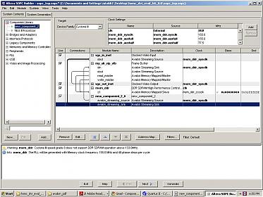
- Subscribe to RSS Feed
- Mark Topic as New
- Mark Topic as Read
- Float this Topic for Current User
- Bookmark
- Subscribe
- Printer Friendly Page