- Mark as New
- Bookmark
- Subscribe
- Mute
- Subscribe to RSS Feed
- Permalink
- Report Inappropriate Content
Hello,
I have a Chinese-made "Altera" USB Blaster.
I opened it, there is a CH552 circuit, a regulator and some resistors.
It is well installed with Windows 10, (Put the driver of the Usb Blaster folder of Altera) recognized by the software TopJtaq or Quartus.
If I connect the pins on an ADSP BF351 it is well recognized with software TopJtag.
If I connect the pins on a Lattice LCMXO256C, I don’t see it.
I studied the datasheet of this component, there must be the SleepN "High" signal to open the Jtag port.
This is good because there is a resistance pullup to 3.3V and checked the level with an oscilloscope.
Of course these components are on the same motherboard, I had to test them one by one, because the chain did not work. (Probably due to the non-recognition of LCMXO256C).
My question: Is this type of USB Blaster compatible with the Lattice LCMXO256C.
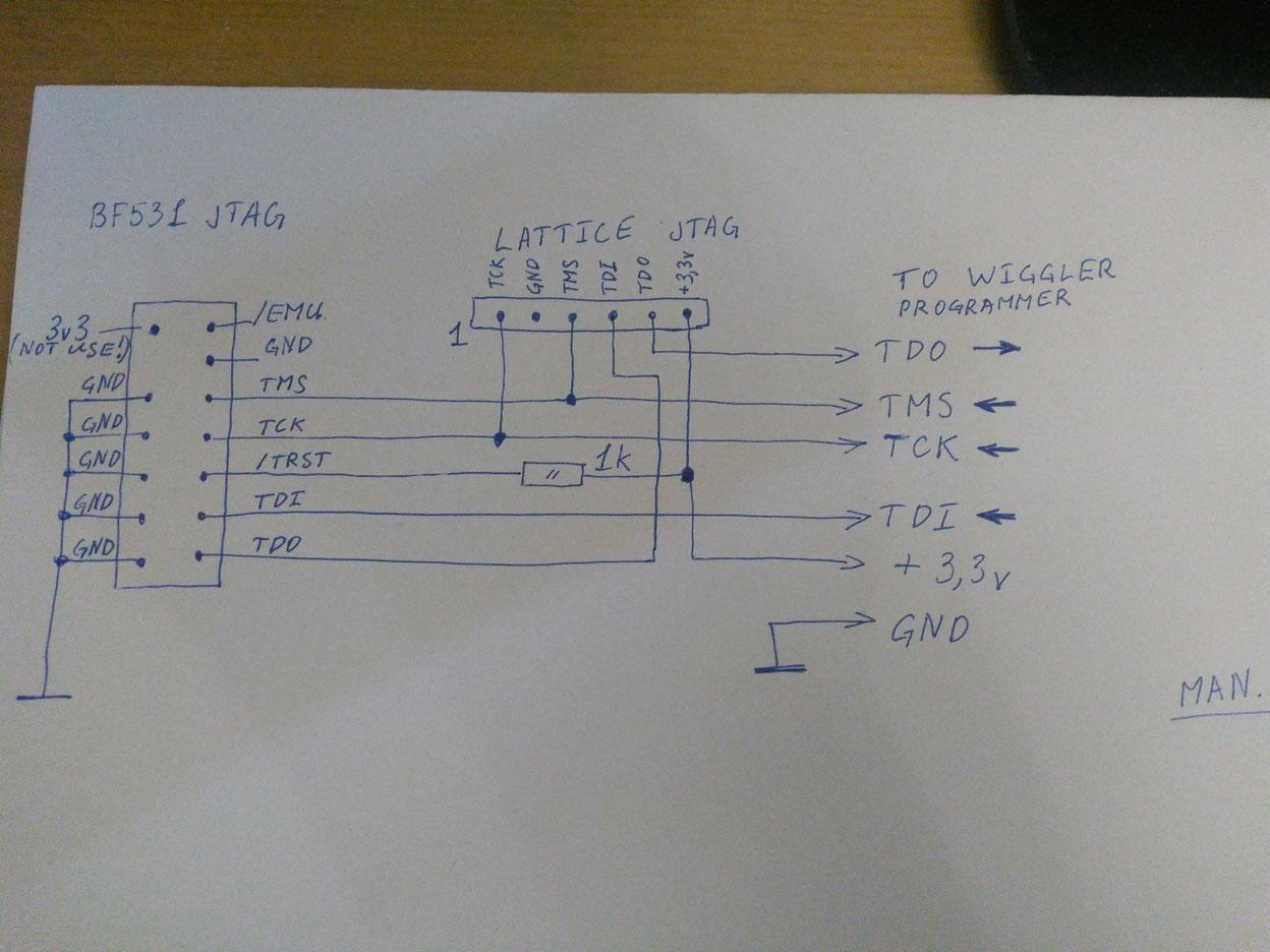
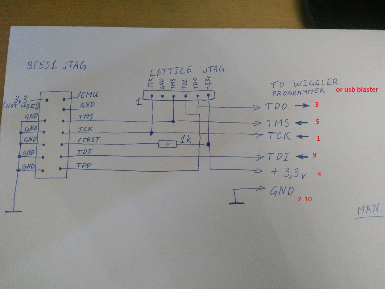
Connection is: TCLK 1, TDO 3, TDI 9, TMS 5, GND 2 or 10 , 3.3v 4 (UL)
Also i try to test with qQuartus, the USB Blaster is recognized, but impossible to see these components one by one.
Nb: it's this time i use it, so I don’t have the knowledge of this software and I may have missed a step.
So I stay focused only on TopJtag
Any idea?
cdt
Link Copied
- Mark as New
- Bookmark
- Subscribe
- Mute
- Subscribe to RSS Feed
- Permalink
- Report Inappropriate Content
- Mark as New
- Bookmark
- Subscribe
- Mute
- Subscribe to RSS Feed
- Permalink
- Report Inappropriate Content
Hello,
USB Blaster II programming cables have 1 chip inside which responsible to decrypt the specific bitstream for Intel FPGA devices. If you use USB Blaster for devices other than Intel FPGA, then it will not work.
regards,
Farabi
- Mark as New
- Bookmark
- Subscribe
- Mute
- Subscribe to RSS Feed
- Permalink
- Report Inappropriate Content
That is not quite accurate is to what goes on inside the USB-Blaster series of device.
Here is a simple block diagram of a USB Blaster. Basically just a USB to byte parallel FIFO transceiver.
Could also use a USB to serial protocol transceiver with the appropriate change in the interface to the
EPM7064 CPLD device.
In particular the USB Blaster knows NOTHING about the Altera/Intel device bitstream or file encoding per se.
It ONLY knows how to twiddle the JTAG lines based on simple commands sent from the host (JAM STAPL here,
or Quartus Programmer, etc).
So the USB Blaster is really a pretty general purpose USB to JTAG interface device that about any host software
could use to interface to JTAG.
/*
 * USB-JTAG, Altera USB-Blaster and compatibles are typically implemented as
 * an FTDIChip FT245 followed by a CPLD which handles a two-mode protocol:
 *
 *            _________
 *           |         |
 *           | AT93C46 |
 *           |_________|
 *            __|__________    _________
 *           |             |  |         |
 *      USB__| FTDI 245BM  |__| EPM7064 |__JTAG (B_TDO,B_TDI,B_TMS,B_TCK)
 *           |_____________|  |_________|
 *            __|__________    _|___________
 *           |             |  |             |
 *           | 6 MHz XTAL  |  | 24 MHz Osc. |
 *           |_____________|  |_____________|
 *
 * Protocol details are given in the code below.
 *
 * It is also possible to emulate this configuration using a single-chip USB
 * controller like the Cypress FX2.
 */
From the comments in the JAM STAPL USB Blaster interface driver describing the USB Blaster protocol. The simplest mode
is to just use the BIT BANGING mode with bit 7 set to zero. Then bits 4,1,0 set TDI, TMS, TCK based on their value. TDO can
be read back by setting bit 6.
That's all the USB Blaster does. Really pretty simple just bit banging the JTAG pins. It does not care what kinds of devices
are connected, just that they follow the JTAG serial protocol.
But the complexity is that you have to send JTAG commands to devices that they understand.
And of course any software that wants to use the USB Blaster to talk JTAG needs to follow the below protocol definition.
/* The following code doesn't fully utilize the possibilities of the
 * USB-Blaster. It only buffers data up to the maximum packet size of 64 bytes.
 *
 * Actually, the USB-Blaster offers a byte-shift mode to transmit up to 504 data
 * bits (bidirectional) in a single USB packet. A header byte has to be sent as
 * the first byte in a packet with the following meaning:
 *
 *   Bit 7 (0x80): Must be set to indicate byte-shift mode.
 *   Bit 6 (0x40): If set, the USB-Blaster will also read data, not just write.
 *   Bit 5..0:     Define the number N of following bytes
 *
 * All N following bytes will then be clocked out serially on TDI. If Bit 6 was
 * set, it will afterwards return N bytes with TDO data read while clocking out
 * the TDI data. LSB of the first byte after the header byte will appear first
 * on TDI.
 */

/* Simple bit banging mode:
 *
 *   Bit 7 (0x80): Must be zero (see byte-shift mode above)
 *   Bit 6 (0x40): If set, you will receive a byte indicating the state of TDO
 *                 in return.
 *   Bit 5 (0x20): Output Enable/LED.
 *   Bit 4 (0x10): TDI Output.
 *   Bit 3 (0x08): nCS Output (not used in JTAG mode).
 *   Bit 2 (0x04): nCE Output (not used in JTAG mode).
 *   Bit 1 (0x02): TMS Output.
 *   Bit 0 (0x01): TCK Output.
 *
 * For transmitting a single data bit, you need to write two bytes. Up to 64
 * bytes can be combined in a single USB packet.
 * It isn't possible to read a data without transmitting data.
 */
- Mark as New
- Bookmark
- Subscribe
- Mute
- Subscribe to RSS Feed
- Permalink
- Report Inappropriate Content
Hi,
We apologize that we are unable to support this case as the USB Blaster was not purchase from Intel. Hence we do not ensure the device quality/functionality and do not provide the further service.
Regards,
Aiman
- Mark as New
- Bookmark
- Subscribe
- Mute
- Subscribe to RSS Feed
- Permalink
- Report Inappropriate Content
Hello,
I come again for the same problem (Sorry)
For more than 15 days I try desperately to read ID code of an LMCOMX256C. (Lattice product)
I tried with Quartus, TopJtag and TopJtagProbe.
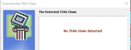
TopJtagProbe has a log, and gives me that it finds an IDCode, which should match nothing or incomplete??
Some idcode(s) collected
NO JTAG chain found
Analyzing the JTAG chain...
TAP reset
DR scan...
Bits to be shifted in:
11111111000000000000000000000000+
00000000000000000000000000000000+
00000000000000000000000000000000+
00000000000000000000000000000000+
00000000000000000000000000000000+
00000000000000000000000000000000+
00000000000000000000000000000000+
00000000000000000000000000000000+
000000000000
Bits shifted out:
11000010000000000000000000000000+
00000000000000000000000000000000+
00000000000000000000000000000000+
00000000000000000000000000000000+
00000000000000000000000000000000+
00000000000000000000000000000000+
00000000000000000000000000000000+
00000000000000000000000000000000+
000000000000
TAP reset
DR scan...
Bits to be shifted in:
11111111000000000000000000000000+
00000000000000000000000000000000+
00000000000000000000000000000000+
00000000000000000000000000000000+
00000000000000000000000000000000+
00000000000000000000000000000000+
00000000000000000000000000000000+
00000000000000000000000000000000+
00000000000000000000000000000000+
00000000000000000000000000000000+
00000000000000000000000000000000+
00000000000000000000000000000000+
00000000000000000000000000000000+
00000000000000000000000000000000+
00000000000000000000000000000000+
00000000000000000000000000000000+
000000000000
Bits shifted out:
11000010000000000000000000000000+
00000000000000000000000000000000+
00000000000000000000000000000000+
00000000000000000000000000000000+
00000000000000000000000000000000+
00000000000000000000000000000000+
00000000000000000000000000000000+
00000000000000000000000000000000+
00000000000000000000000000000000+
00000000000000000000000000000000+
00000000000000000000000000000000+
00000000000000000000000000000000+
00000000000000000000000000000000+
00000000000000000000000000000000+
00000000000000000000000000000000+
00000000000000000000000000000000+
000000000000
.......
Checking for all bits are either ones or zeros...
Last 500 bits we received are either only ones or only zeros
JTAG chain NOT found, checking for Atmel ATmega bug...
Reçu des bits ont deux ones et zeros
IDCODE register
11000010000000000000000000000000
.......
On the attached example, you will be able to see a case that works in string extracted from another forum. (This is the result I should have)
As it never worked in chain, I remind you that I tested the components one by one.
This works for the analog device BF532, but never for lattice with my USB Blaster.
I have read literature about this problem on the net, there are often this case cited.
It is explained that the connection must be modified by adding resistance/+ capacitor, especially on the clock.
I didn’t try anything.
For the case cited as an example, this was done with a WIGGLER connection, so on a sponsor port.
So I’m wondering, is there not a speed problem or what like that?
1) So I wonder if this component is "referenced" in these softwares or that it should appear in all cases even if it is a new one. Then the BDSL file of the manufacturer would be important. Or device not compatible with these sotfware??
2nd) I would like to try with the Quartus string debugger, but I don’t know the commands to enter.
If someone could give me an example (Copy screen), I think there are only 3 fields to fill in (command, TAP State and clock) and do it several times. I think you understood me
I thing that this chinesse USB Blaster work
here the init:
Creating CrUsbBlaster
Loading USB-Blaster FTD2XX interface:
Loading usbblstr32.dll ... OK
Found 1 USB-Blaster device(s)
Destroying CrUsbBlaster
Creating cable object ALTERA_USB_BLASTER
Creating CrUsbBlaster
Loading USB-Blaster FTD2XX interface:
Loading usbblstr32.dll ... OK
Device successfully opened
Initialization succeeded
Thank's for your help
- Mark as New
- Bookmark
- Subscribe
- Mute
- Subscribe to RSS Feed
- Permalink
- Report Inappropriate Content
Have you tried posting on a Lattice Semi FPGA support forum?
I would think this topic would be much more relevant there and you might get some help.
And I'm still not sure why you are trying to use an Altera USB Blaster to do what you are doing.
- Subscribe to RSS Feed
- Mark Topic as New
- Mark Topic as Read
- Float this Topic for Current User
- Bookmark
- Subscribe
- Printer Friendly Page