- Mark as New
- Bookmark
- Subscribe
- Mute
- Subscribe to RSS Feed
- Permalink
- Report Inappropriate Content
Hi everyone,
My current design is clocked by a 250MHz master clock. Within the FPGA, I use a divide by 16 PLL with two clock outputs c0, c1 with different phase in order 1) to clock RAM blocks (with c0) 2) to load (with c1) a shift register that serialize the RAM output data. To properly phased these two clocks, I'd like to view them with the simulator. Does QII allows for viewing the PLL outputs with a functionnal simulation (to avoid a long compilation time) ? If not, is it necessary to attach output pins to these internal (buried ?) clocks to be able to view them after the timing analysis ? And what's up when I will remove those output pins (I don't need to output these clocks outside the FPGA !), could this change the timing ? Thanks ! OliverLink Copied
- Mark as New
- Bookmark
- Subscribe
- Mute
- Subscribe to RSS Feed
- Permalink
- Report Inappropriate Content
Technically, you should be able to find the outputs of the PLL in a functional sim, and I believe they should be delayed correctly, but it will be an ideal delay, i.e. exactly what you entered into the PLL settings.
But you really don't want to use the simulator to analyze paths between domains. You have to check each register to register path between the domains(unless you trust a few represent them all). You have to check them on every compile(or trust things never change). What you really want to do is static timing analysis between the domains, to guarantee data transfers properly between them. That being said, by entering the clock constraints in the PLL, timin analysis already knows how they're related, so there's probably not much, if any, to do. (I would recommend using TimeQuest, in which case you need to put a clock constraint on the input clock and a derive_pll_clocks command). In TimeQuest you can report timing on specific paths, i.e. you can list all paths from c0 to c1.- Mark as New
- Bookmark
- Subscribe
- Mute
- Subscribe to RSS Feed
- Permalink
- Report Inappropriate Content
--- Quote Start --- I would recommend using TimeQuest, in which case you need to put a clock constraint on the input clock and a derive_pll_clocks command. --- Quote End --- Or "derive_pll_clocks -create_base_clocks", which will make TimeQuest use the PLL megafunction settings to automatically produce the create_clock on the base clock feeding the PLL as well as the generated clocks driven by the PLL.
- Mark as New
- Bookmark
- Subscribe
- Mute
- Subscribe to RSS Feed
- Permalink
- Report Inappropriate Content
Rysc,
Indeed, I've been able to view my PLL output clocks in a functional sim. In the end, it simply showed me the signals were ...as required in the PLL settings ! I usually have a great confidence in Qts but for this time, I had a doubt because of a "strange" sample behavioral waveforms (see enclosed) generated for my PLL design and likely due to a too much short displayed waveform time period. Many Thanks to both of you for sharing your experience in this forum ! Your answers give precious clues and encouragement that help me for a deeper reading of the pretty complex "PLL & Clock networks" chapter of the Stratix II device handbook (that I would have sub-titled "36 ways to loose your clocks in a labyrinth" ;-) ) Oliver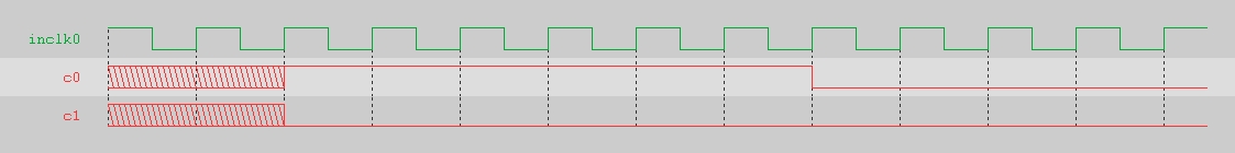
- Mark as New
- Bookmark
- Subscribe
- Mute
- Subscribe to RSS Feed
- Permalink
- Report Inappropriate Content
I'm still not sure where you're having problems and are trying to figure out. The PLL should do a very good job of aligning the clock as you request. There will be a small variance due to global clock tree routing, but that will be on the orger of picoseconds. What is it that you're trying to see? Note that a functional simulation, doesn't know anything about the actual device, so there will be no timing info except what you put into it. Static Timing Analysis is the method for finding delays.
- Subscribe to RSS Feed
- Mark Topic as New
- Mark Topic as Read
- Float this Topic for Current User
- Bookmark
- Subscribe
- Printer Friendly Page