- Mark as New
- Bookmark
- Subscribe
- Mute
- Subscribe to RSS Feed
- Permalink
- Report Inappropriate Content
Hi,
I’m using the ALTDDIO intellectual property but I have problems with it.
The ALTDDIO-Input works very well.
The ALTDDIO-Output does not work. I generate a clock, input signals (reset, data_in) but the output of the component is always 0. I check the reset signal. In the simulation it works well.
Can you help me?
Thanks
Bryan
ALTDDIOOUT_inst1 : ALTDDIOOUT -- MY code
PORT map
(
aclr => reset, --signal active high
outclock => clock_200MHz, -- clock
datain_h => d_ram_out_1h, --x”AAAAA”
datain_l => d_ram_out_1l, --x”55555”
dataout => D_RAM(17 downto 0) -- remain x“00000”
);
- Mark as New
- Bookmark
- Subscribe
- Mute
- Subscribe to RSS Feed
- Permalink
- Report Inappropriate Content
Hi,
I discovered that the ALTDDIO works but I can not monitor its output with Signal-tap.
Thank you for the support.
BR
Bryan
Link Copied
- Mark as New
- Bookmark
- Subscribe
- Mute
- Subscribe to RSS Feed
- Permalink
- Report Inappropriate Content
Hi @BIdro
1) Confirm in RTL viewer that your block is connected correctly? make sure nothing is synthesized away.
2) Check if there is any Quartus Warning messages that can give you extra clue.
3) Confirm the reset is correct. You can try to use an In-System Source and Probe as reset. Then you can manually toggle it. Or you can confirm it in SignalTap.
4) Confirm the clock is correct. Make sure it is toggling.
- Mark as New
- Bookmark
- Subscribe
- Mute
- Subscribe to RSS Feed
- Permalink
- Report Inappropriate Content
Hi JonWay,
The name of my component is PROVA2.
1- Yes, I confirm that the component is connected in the RTL viewer. (see ALTDDIO_1)
2- The only warning refers to clock (see ALTDDIO_2)
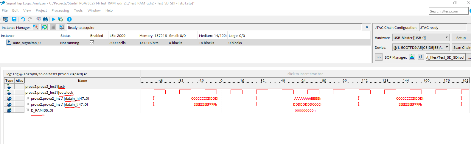
3-4- Yes, I confirm that clock is toggling. (see ALTDDIO_0)
I try the reset/aclr at '0', at '1' and to toggle it.
I'm using Quartus 18.1.
Thanks
Bryan
- Mark as New
- Bookmark
- Subscribe
- Mute
- Subscribe to RSS Feed
- Permalink
- Report Inappropriate Content
I believe you can get rid of that warning by constraining your clocks. See similar case: https://community.intel.com/t5/Intel-Quartus-Prime-Software/CLOCK-50-was-determined-to-be-clock-but-was-found-without-an/td-p/261272
As for the signaltap, are you using the outclock as your STP clock? Im not sure if the STP not capturing the output, but the fact is it is toggling on the output pin...you might want to confirm with a scope.
If it is really not toggling on the output pin, you might want to reduce the design to a width of 2 and check if this works. I see that your input and output bit width are not the same. I expected that your data_l and data_h and your dataout bus width is the same.
- Mark as New
- Bookmark
- Subscribe
- Mute
- Subscribe to RSS Feed
- Permalink
- Report Inappropriate Content
I used as STP clock the ALTDDIO's outclock and another 200 MHz frequency clock. I reduced the width at 2. I put the output signals in 2 test-points to measure with ocilloscope. The result is that in Signal Tap test-points remain '0' and I measure 0 Volt with oscilloscope.
Thanks for the help.
Bryan
- Mark as New
- Bookmark
- Subscribe
- Mute
- Subscribe to RSS Feed
- Permalink
- Report Inappropriate Content
To rule out if this is hardware issue, can you try the simple design on a Cyclone V development kit?
- Mark as New
- Bookmark
- Subscribe
- Mute
- Subscribe to RSS Feed
- Permalink
- Report Inappropriate Content
Hi,
I try to use the IP in the evaluation board DE1-SoC board (http://de1-soc.terasic.com).
The IP output pins remain at '0' like in the other board when I started.
Is it possible that there is a version problem? I'm using Quartus 18.1 standard edition.
Thanks.
Bryan
- Mark as New
- Bookmark
- Subscribe
- Mute
- Subscribe to RSS Feed
- Permalink
- Report Inappropriate Content
Hi, It could either be a Quartus version or a design issue.
You can try to use the 18.1 version
and
also you can try the example design from this link:
- Mark as New
- Bookmark
- Subscribe
- Mute
- Subscribe to RSS Feed
- Permalink
- Report Inappropriate Content
Hi,
I discovered that the ALTDDIO works but I can not monitor its output with Signal-tap.
Thank you for the support.
BR
Bryan
- Subscribe to RSS Feed
- Mark Topic as New
- Mark Topic as Read
- Float this Topic for Current User
- Bookmark
- Subscribe
- Printer Friendly Page