- Mark as New
- Bookmark
- Subscribe
- Mute
- Subscribe to RSS Feed
- Permalink
- Report Inappropriate Content
In some examples,I can see they just add some timing constraints in sdc file,for example,"create_clock -period 1.552 [get_ports TenGbE_RefClk]".
But PIN_AK7 is only a 100MHz clock described in DE5-Net User Manual.pdf,and in Signal Tap Logic Analyzer,it's really just 100MHz , I don't know why, anyone can help me? thanks!
Link Copied
- Mark as New
- Bookmark
- Subscribe
- Mute
- Subscribe to RSS Feed
- Permalink
- Report Inappropriate Content
- Mark as New
- Bookmark
- Subscribe
- Mute
- Subscribe to RSS Feed
- Permalink
- Report Inappropriate Content
Yes,maybe you are right,I need confige the oscillators
- Mark as New
- Bookmark
- Subscribe
- Mute
- Subscribe to RSS Feed
- Permalink
- Report Inappropriate Content
- Mark as New
- Bookmark
- Subscribe
- Mute
- Subscribe to RSS Feed
- Permalink
- Report Inappropriate Content
Thanks for your reply, I do generate a 322MHz clock.
Now, I connect 10g MAC and 10gbase-r PHY appropriately, and I only configured the register 0x1200、0x1201 and 0x1202 of 10g MAC, the output interface of SFP is directly connected to it's input interface. However, the signal link_fault_status_xgmii_tx_data is always 01.
I tryed to use csr_clk of 10g MAC in 50MHz、125MHz and156MHz, but it does not work,I don't know why?
Is there anything other I forgot to configure???
- Mark as New
- Bookmark
- Subscribe
- Mute
- Subscribe to RSS Feed
- Permalink
- Report Inappropriate Content
- Mark as New
- Bookmark
- Subscribe
- Mute
- Subscribe to RSS Feed
- Permalink
- Report Inappropriate Content
Thanks for your reply,
I read register 0x082 of transceiver, and the readdata is 0x00000084,rx_ready and tx_ready are all high level, it seems well,but the signal link_fault_status_xgmii_tx_data is still 01.
My project is based on 10G reference design under install director.
- Mark as New
- Bookmark
- Subscribe
- Mute
- Subscribe to RSS Feed
- Permalink
- Report Inappropriate Content
- Mark as New
- Bookmark
- Subscribe
- Mute
- Subscribe to RSS Feed
- Permalink
- Report Inappropriate Content
I tried to simulate the example that you shared, but I got lots of errors.
The value of register 0x082 indicate that HI_BER ,BLOCK_ LOCK,TX_FIFO_FULL,RX_FIFO_FULL,RX_SYNC_HEAD_ERROR,RX_SCRAMBLER_ERROR,RX__DATA_READY all in right status.
So, how to verify other possible factors (1) to (5) above?
Thanks.
- Mark as New
- Bookmark
- Subscribe
- Mute
- Subscribe to RSS Feed
- Permalink
- Report Inappropriate Content
Hi,
For the sim error issue debug
- This is referring to the wiki reference design that I shared with you earlier.
- I test run the wiki design myself and the sim error that I saw was "missing sim library files". This is due to the wiki design doesn't go through the Quartus compilation stage yet.
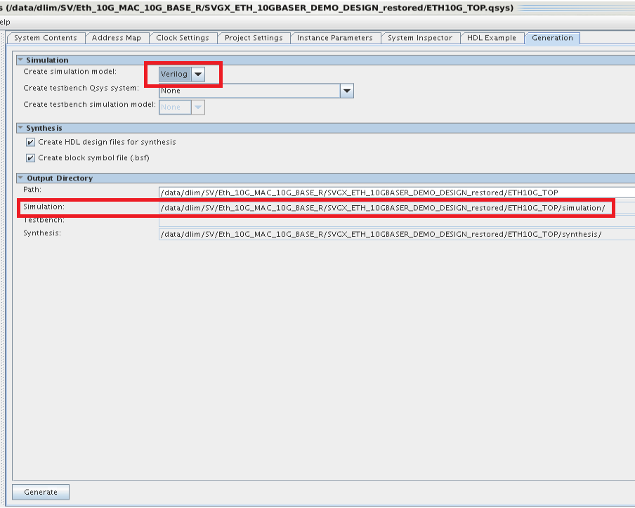
- Below is how you can fix the sim error issue (refer to attached pic as well)
- Move the QSYS file to same hierarchy as Quartus project folder
- Open QSYS, set verilog for simulation library, then click generate QSYS to generate the sim library file for the IP
- Finally launch modelsim again and run the compile.tcl script and it should works this time
For the hardware debug suggestion 1 to 5
- I am not quite sure which register 0x082 that you are referring to here. Can you elaborate further on this register ?
- Before that, you should make sure the Ethernet design setting matches with your board hardware.
- My instruction on debug suggestion 1 to 5 should be pretty clear. Any part that still confuse you ?
Thanks.
Regards,
dlim
- Mark as New
- Bookmark
- Subscribe
- Mute
- Subscribe to RSS Feed
- Permalink
- Report Inappropriate Content
- Mark as New
- Bookmark
- Subscribe
- Mute
- Subscribe to RSS Feed
- Permalink
- Report Inappropriate Content
- Subscribe to RSS Feed
- Mark Topic as New
- Mark Topic as Read
- Float this Topic for Current User
- Bookmark
- Subscribe
- Printer Friendly Page