- Mark as New
- Bookmark
- Subscribe
- Mute
- Subscribe to RSS Feed
- Permalink
- Report Inappropriate Content
Hi,
I am bringing up the transceiver in the Stratix 10 MX development kit using both approaches below
APPROACH (A)
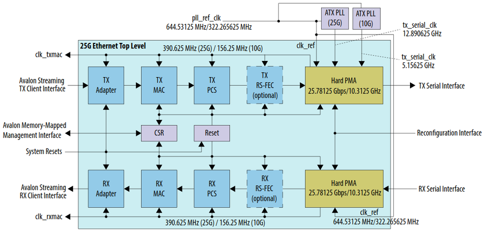
I followed the 25G Ethernet Intel Stratix 10 FPGA IP User Guide.
My implementation steps:
1) Generate the example design 10/25G Ethernet Intel Stratix 10
2) Change the top-level, QSF, and SDC files corresponding to the S10MX board (using the golden example file from HERE)
3) Connect the transceiver reference clock to 644.53125 clock source.
I tested with QSFP Port 0 and 1 at 10G mode, and always received RX_MAC error, i.e. l1_rx_error = 0x3 or 0x4
APPROACH (B)
I followed the Low Latency Ethernet 10G MAC Intel Stratix 10 FPGA IP Design Example User Guide
My implementation steps:
1) Generate the example design Low Latency Ethernet 10G
2) Change the top-level, QSF, and SDC files corresponding to the S10MX board (using the golden example file from HERE)
3) Change the ref_clk_clk to 644.5312 MHz. Then reconfigure
- fPLL: ref_clk =644.5312 MHz. outclk_div1 = 312.5 MHz, outclk_div2 = 156.25 MHz
- ATX PLL: ref_clk = 644.5312 MHz
- PHY: rx_cdr_refclk0 = 644.5312 MHz
4) Change csr_clk to either 100 or 125 MHz. Then reconfigure Reset Synchronizer: ref_clk = 100 or 125 MHz.
I tested the design with
- QSFP Port 0: All 4 channels got local faults
- QSFP Port 1: channel 0 passed (both TX and RX are Idle). Channel 1, 2, 3 got local faults
The setting is pretty straightforward. Is there any way to figure out where the problem is?
Thanks
Link Copied
- Mark as New
- Bookmark
- Subscribe
- Mute
- Subscribe to RSS Feed
- Permalink
- Report Inappropriate Content
Hi,
The 10G example design use only 1 lane. You might need to double-check which lane that you are actually connected from the board schematic. Perhaps, you may try to connect with a QSFP loopback module to ensure the design is working first before connecting with others.
Besides, you may start with the 10GBASE-R Ethernet design example, and use 322Mhz as a reference clock. See the link below:
https://www.intel.com/content/dam/www/programmable/us/en/pdfs/literature/ug/ug-20073.pdf
Regards -SK
- Mark as New
- Bookmark
- Subscribe
- Mute
- Subscribe to RSS Feed
- Permalink
- Report Inappropriate Content
Hi,
Thank for your reply.
Do you refer lane as channel? I modify the example design to support 4 channels, each channel 10G. I also tested the design with QSFP28 Port 0 and Port 1, but neither worked properly.
I already tested the network with an Arria 10 board beforehand. So I am pretty sure it was not the network issue.
My approach (B) is based on the document you have sent.
The Intel S10MX board only provide QSFP reference clock of 644.5312 MHz. That's why I modified the ref_clk settings in the PHY, ATX, and fPLL module to 644 MHz.
PHY setting: modifychange CDR reference clock
ATX PLL setting: modify PLL auto mode reference clock
altera_xcvr_atx_pll_ip atx_pll_inst(
    .pll_refclk0(ref_clk_clk),
    .tx_serial_clk(tx_serial_clk),
    .pll_locked(atx_pll_locked)
);
fPLL setting: modify PLL integer mode reference clock
pll fpll_inst (
    .pll_refclk0    (ref_clk_clk),
    .pll_cal_busy   (),
    .outclk_div2    (core_clk_156),             // 156.25MHz clock
    .outclk_div1    (core_clk_312),             // 312.50MHz clock
    .pll_locked     (core_pll_locked)
);
Top-level file
module altera_eth_top  # (

        parameter NUM_CHANNELS  = 4,
        parameter DEVICE_FAMILY = "Stratix 10"

 )(

    input   wire            CLK_SYS_100M_P,
	 input   wire 				 CLK_DDR4_COMP_P,
    input   wire            refclk_zqsfp0_p,
	 input   wire            refclk_zqsfp1_p,
    input   wire            CPU_RESETN,
	 output  wire [NUM_CHANNELS-1:0]         zqsfp0_tx_p,
    input   wire [NUM_CHANNELS-1:0]         zqsfp0_rx_p,
	 output  wire [NUM_CHANNELS-1:0]         zqsfp1_tx_p,
    input   wire [NUM_CHANNELS-1:0]         zqsfp1_rx_p,
	 output          zqsfp0_1v8_modsel_l   ,
    output          zqsfp0_1v8_reset_l    ,
    input           zqsfp0_1v8_modprs_l   ,
    output          zqsfp0_1v8_lpmode     ,
    input           zqsfp0_1v8_int_l,
	 output          zqsfp1_1v8_modsel_l   ,
    output          zqsfp1_1v8_reset_l    ,
    input           zqsfp1_1v8_modprs_l   ,
    output          zqsfp1_1v8_lpmode     ,
    input           zqsfp1_1v8_int_l,
	 inout           zqsfp_s10_i2c_sda     ,
    output          zqsfp_s10_i2c_scl
);

	wire                            ninit_done;

	 assign zqsfp1_1v8_lpmode        = 1'b0;
    assign zqsfp1_1v8_modsel_l      = 1'b0;
    assign zqsfp1_1v8_reset_l       = 1'b1; //CPU_RESETN && ~ninit_done;

	 assign zqsfp0_1v8_lpmode        = 1'b0;
    assign zqsfp0_1v8_modsel_l      = 1'b0;
    assign zqsfp0_1v8_reset_l       = 1'b1; // CPU_RESETN && ~ninit_done;
	 assign zqsfp_s10_i2c_sda        =  1'bz;
	 assign zqsfp_s10_i2c_scl        =  1'bz;

	 wire            core_clk_312;
    // LED
    wire [NUM_CHANNELS-1:0]          block_lock_n;
    wire [NUM_CHANNELS-1:0]          tx_ready_export_n;
    wire [NUM_CHANNELS-1:0]          rx_ready_export_n;

    // debug clock
    wire            core_clk_156;

    wire             core_pll_locked_n;
    wire             atx_pll_locked_n;

    wire [NUM_CHANNELS-1:0]       avalon_st_rxstatus_valid_156;
    wire [NUM_CHANNELS-1:0][39:0] avalon_st_rxstatus_data_156;
    wire [NUM_CHANNELS-1:0][6:0]  avalon_st_rxstatus_error_156;

wire                            csr_rst_n;
wire                            tx_rst_n;
wire                            rx_rst_n;

wire [NUM_CHANNELS-1:0]         block_lock;
wire [NUM_CHANNELS-1:0]         tx_ready_export;
wire [NUM_CHANNELS-1:0]         rx_ready_export;
wire                            core_pll_locked;
wire                            atx_pll_locked;

wire csr_clk;
assign csr_clk = CLK_SYS_100M_P;

assign block_lock_n = ~block_lock;
assign tx_ready_export_n = ~tx_ready_export;
assign rx_ready_export_n = ~rx_ready_export;
assign core_pll_locked_n = ~core_pll_locked;
assign atx_pll_locked_n = ~atx_pll_locked;

// Reset Release module
reset_release reset_release_inst(
        .ninit_done (ninit_done)
);

altera_eth_10g_mac_base_r #(
        .NUM_CHANNELS(NUM_CHANNELS),
        .DEVICE_FAMILY(DEVICE_FAMILY)
    ) dut_inst (

    .csr_clk            (csr_clk),
    .csr_rst_n          (CPU_RESETN && ~ninit_done),
    .core_clk_312       (core_clk_312),
    .tx_rst_n           (CPU_RESETN && ~ninit_done),
    .rx_rst_n           (CPU_RESETN && ~ninit_done),
    .ref_clk_clk        (refclk_zqsfp1_p),

    .core_clk_156       (core_clk_156),

    // csr interface
    .csr_read           (1'b0),
    .csr_write          (1'b0),
    .csr_writedata      (32'b0),
    .csr_readdata       (),
    .csr_address        (16'b0),
    .csr_waitrequest    (),

    .tx_ready_export    (tx_ready_export),
    .rx_ready_export    (rx_ready_export),
    .block_lock         (block_lock),

    .tx_serial_data     (zqsfp1_tx_p),
    .rx_serial_data     (zqsfp1_rx_p),
    .core_pll_locked    (core_pll_locked),
    .atx_pll_locked     (atx_pll_locked),

    .avalon_st_rxstatus_valid_156           (avalon_st_rxstatus_valid_156),
    .avalon_st_rxstatus_data_156            (avalon_st_rxstatus_data_156),
    .avalon_st_rxstatus_error_156           (avalon_st_rxstatus_error_156)
);

endmodule
Thanks
- Mark as New
- Bookmark
- Subscribe
- Mute
- Subscribe to RSS Feed
- Permalink
- Report Inappropriate Content
- To narrow down the problem, this is still good to know if the design can operate as expected by using the QSFP loopback module?
- Does the rx_is_lockedtodata is always asserted? Or it is toggling? What is the status of the tx_fifo_full and rx_fifo_full?
- Do you observe the avalon_st_tx_ready signal is asserted?
- Could you do a sanity check by changing the VCCR_GXB to 1_1v?
Regards -SK
- Mark as New
- Bookmark
- Subscribe
- Mute
- Subscribe to RSS Feed
- Permalink
- Report Inappropriate Content
If further support is needed in this thread, please post a response within 15 days. After 15 days, this thread will be transitioned to community support. The community users will be able to help you with your follow-up questions.
- Subscribe to RSS Feed
- Mark Topic as New
- Mark Topic as Read
- Float this Topic for Current User
- Bookmark
- Subscribe
- Printer Friendly Page


