- Mark as New
- Bookmark
- Subscribe
- Mute
- Subscribe to RSS Feed
- Permalink
- Report Inappropriate Content
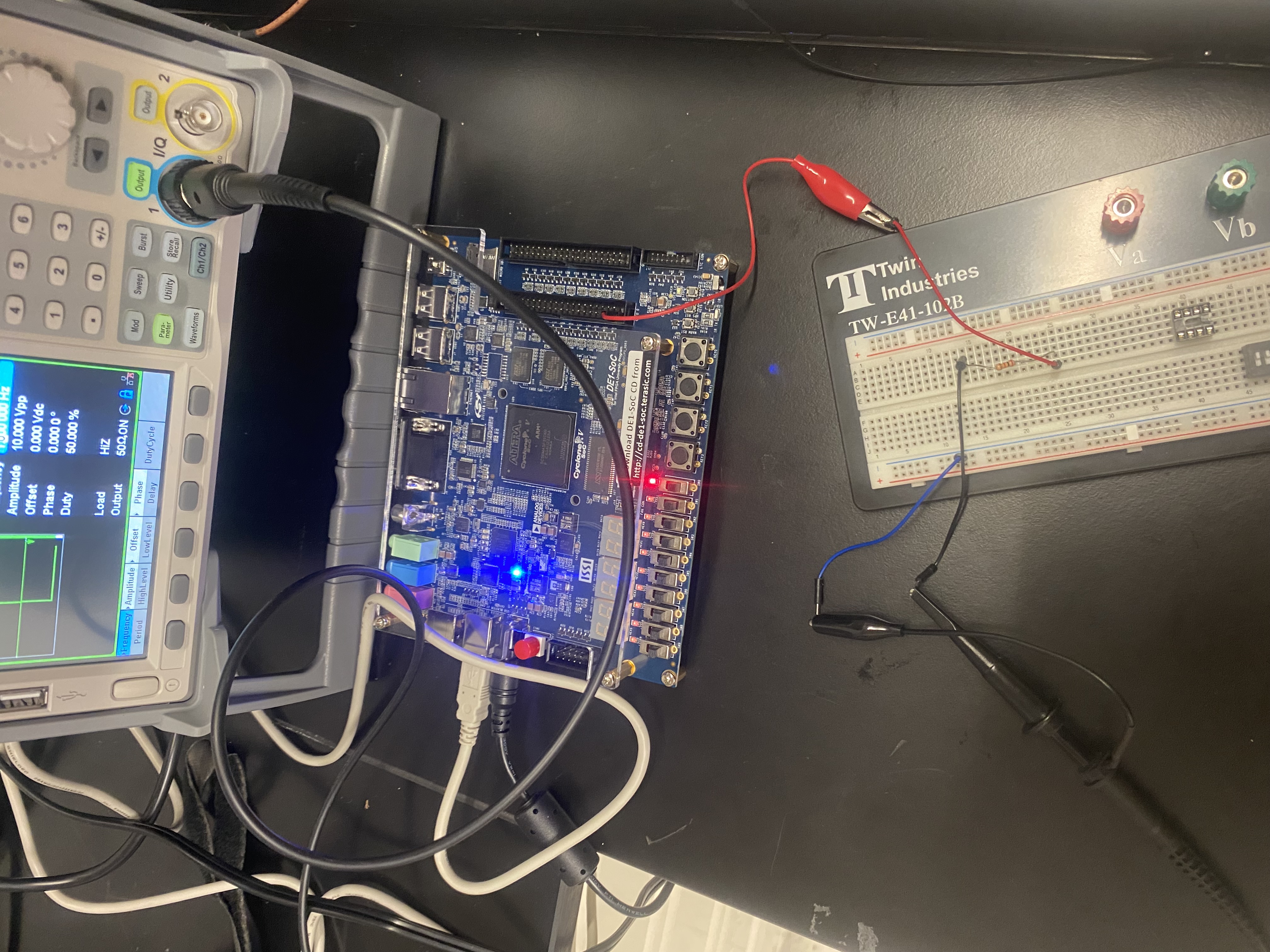
I want to take square wave with 1Hz frequency (50% duty cycle) generated from a function generator as input to the FPGA board (Cyclone V, 5CSEMA5F31C6N). I am trying to give a square pulse of 1hz as input to the FPGA. So to test how to take an input from an external source I wrote the following basic code:
module frequency(input imp,
           output op);
assign op = imp;
endmodule
The function generator output was given to the GPIO_0[0] (PIN_AC18) and output pin was chosen as: LEDR[0]. When I upload the program after pin assignment, the LEDR0 only remains high, it does not blink from high to low (since square wave oscillates from 0 to 1 and 1 to 0 at each clock cycle.
How can I solve the issue ? How can I read a digital signal from the function generator in the FPGA ?
Link Copied
- Mark as New
- Bookmark
- Subscribe
- Mute
- Subscribe to RSS Feed
- Permalink
- Report Inappropriate Content
Hi,
the photo suggests that you have no ground connection between generator and FPGA board, only (red) signal line. Also the oscilloscope probe used to send function generator output is probably a 10:1 probe, involving a large series resistance.
According to photo, you are also feeding GPIO_0_34 (JP1 pin 39) rather than GPIO_0_0 (JP1 pin 1).
Just in case, notice that input voltage must not exceed the range of 0..3.3 V.
Regards
Frank
- Mark as New
- Bookmark
- Subscribe
- Mute
- Subscribe to RSS Feed
- Permalink
- Report Inappropriate Content
Hello Frank,
Thank you very much. My pin planning was wrong. Now it works.
-Daiyan.
- Subscribe to RSS Feed
- Mark Topic as New
- Mark Topic as Read
- Float this Topic for Current User
- Bookmark
- Subscribe
- Printer Friendly Page