- Mark as New
- Bookmark
- Subscribe
- Mute
- Subscribe to RSS Feed
- Permalink
- Report Inappropriate Content
I am working on a design using an Agilex F-series part (AGFB014R24B2E3V) and am having issues with tri-stated outputs. The RTL in question is:
assign TRIG[0] = (lb_enable_dd) ? clk_fast : 1'bz;
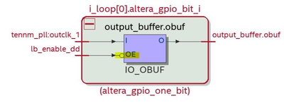
When I test my board, I found it to be inverted. If I set lb_enable_dd high, it was hi-z, low gave me clk_fast on my TRIG[0] output. When I opened the Technology Map View (post-fit) I noticed the IO_OBUF primitive had a inverter on the OE input that didn't seem to be compensated for in compile.
Things I have tried:
- Tested both 21.2 and 21.3 versions of the tools.
- Switching to a non-tristating output. This works as expected, no polarity issues.
assign TRIG[0] = (lb_enable_dd) ? clk_fast : 1'b0;
- Tried generating the buffer using the GPIO Intel FPGA IP core from the library.
trig_out trig_out (
.din ({lb_rxclk_det[0], clk_fast, lb_enable_dd, clk_fast}),
.oe ({4{lb_enable_dd}}),
.pad_out (TRIG[3:0])
);
Same inverter present on the IO_OBUF. Even when I open the datasheet for that IP core it says OE should be active high.
Thoughts?
Link Copied
- « Previous
-
- 1
- 2
- Next »
- Mark as New
- Bookmark
- Subscribe
- Mute
- Subscribe to RSS Feed
- Permalink
- Report Inappropriate Content
@ShengN_Intel
"The bubble is to indicate the inversion to compensate for the active low oe port of the obuf. So, what you see in the tech map view is actually correct."
Active low port unfortunately isn't indicated in the symbol, otherwise it would be designated nOE, OE# or similar. I see what you mean, but technology map schematic doesn't comply with commonly understood logic symbol presentation, although it's used "since ever" in Quartus. It's prone to misunderstanding as shown by this thread.
Best regards
Frank
- Mark as New
- Bookmark
- Subscribe
- Mute
- Subscribe to RSS Feed
- Permalink
- Report Inappropriate Content
Hi @FvM
The resource property viewer shows it's an active low oe check screenshot below:
Thanks,
Regards,
Sheng
- Mark as New
- Bookmark
- Subscribe
- Mute
- Subscribe to RSS Feed
- Permalink
- Report Inappropriate Content
@ShengN_Intel
I have no problems to find out what the actual logic function is. Problem is that logic symbol in technology map schematic is wrong. The "!" inversion indicator isn't reflected.
- Mark as New
- Bookmark
- Subscribe
- Mute
- Subscribe to RSS Feed
- Permalink
- Report Inappropriate Content
It needs to zoom in to the resource property viewer to see the inversion indicator.
It wouldn't shown in technology map viewer logic symbol. I think this causes the confusion.
- Subscribe to RSS Feed
- Mark Topic as New
- Mark Topic as Read
- Float this Topic for Current User
- Bookmark
- Subscribe
- Printer Friendly Page
- « Previous
-
- 1
- 2
- Next »


