- Mark as New
- Bookmark
- Subscribe
- Mute
- Subscribe to RSS Feed
- Permalink
- Report Inappropriate Content
Hello,
my name is Mustapa Hussainar and i need help in generating a program that can on and off two or more LEDs in interleaving method. im a beginner in VHDL and FPGA and its important for me to learn this things. For now i have done single LED blinking project using clock divider, comparator and lpm counter. therefore i think the next step is to learn how to generate interleave pwm switching to turn on and off the LED. im using Quartus II software and an Altera DE2-70. Hope you guys can help me with the logic needed to generate multiple pwm signals that uses the same duty cycle but out of phase with each other. Thank you Regards, Mustapa HussainarLink Copied
7 Replies
- Mark as New
- Bookmark
- Subscribe
- Mute
- Subscribe to RSS Feed
- Permalink
- Report Inappropriate Content
Hi Mustapa,
I can't understand what is the problem: duplicate or extend what you have already done for a single LED. If I correctly understand what you ask is quite straightforward. Anyway, you'd better try to write some code and post it if you have issues. You'll hardly receive help here in the forum if you simply ask someone to write all the code for you.- Mark as New
- Bookmark
- Subscribe
- Mute
- Subscribe to RSS Feed
- Permalink
- Report Inappropriate Content
--- Quote Start --- Hi Mustapa, I can't understand what is the problem: duplicate or extend what you have already done for a single LED. If I correctly understand what you ask is quite straightforward. Anyway, you'd better try to write some code and post it if you have issues. You'll hardly receive help here in the forum if you simply ask someone to write all the code for you. --- Quote End --- Hi Cris, thank you for replying to me. What i want to do is to have the second LED to light on right after the first LED lights off, yes its quite straightforward. I know i need another comparator for the second PWM signal but i dont know how to make the second signal to start instantaneously after the first signal become '0', below is the code for my first comparator with a count modulus of 100 and clock divider frequency of 100MHz. Library ieee; use ieee.std_logic_1164.all; use ieee.std_logic_unsigned.all; entity comparator is port( q, b : in std_logic_vector( 6 downto 0); c : out std_logic); end comparator; architecture body3 of comparator is begin process (q, b) begin if (q<= b) then c<='1'; else c<='0'; end if; end process; end body3; if i make changes like this to the code for the second comparator, begin if (c<=1) then c2<='0'; else if (q<= b) then c2<='1'; would it be correct?
- Mark as New
- Bookmark
- Subscribe
- Mute
- Subscribe to RSS Feed
- Permalink
- Report Inappropriate Content
Hi mushussain ,
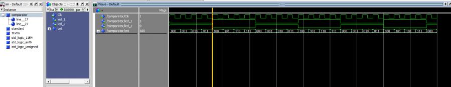
You can use PLL and Counter IP from QSYS. or find the code below and modify as per your requirement. Check the attached image. https://alteraforum.com/forum/attachment.php?attachmentid=14324&stc=1
Library ieee;
use ieee.std_logic_1164.all;
use ieee.std_logic_unsigned.all;
entity comparator is
port( Clk:in std_logic;
    led_1: out std_logic;
    led_2: out std_logic
);
end comparator;
architecture body3 of comparator is
signal cnt:std_logic_vector(2 downto 0):=(others=>'0');
begin
process (clk)
begin
 if rising_edge(clk) then
  cnt<=cnt+'1';
   if(cnt="111")then
    cnt<=(others=>'0');
   end if;
  end if;
end process;
process (clk,cnt)
begin
 if (cnt<="011")then
  led_1<='0';
  led_2<='1';
 else
  led_1<='1';
  led_2<='0';
 end if;
end process;
end body3;
Best Regards, Anand Raj Shankar (This message was posted on behalf of Intel Corporation)
- Mark as New
- Bookmark
- Subscribe
- Mute
- Subscribe to RSS Feed
- Permalink
- Report Inappropriate Content
You can do it with a single modified comparator entity: you simply need to add another compare input (b2) and another status output (c2).
Here is a very naive example; modify it according to the desired LED behavior.
process (q, b1, b2, c1, c2)
 begin
    if (q<= b1)   then
       c1<='1'
       c2<='0';
   elsif (q<=b2) then
      c1<='0'
      c2<='1';
   else
     c1<='0'
     c2<='0';
   end if;
end process;
- Mark as New
- Bookmark
- Subscribe
- Mute
- Subscribe to RSS Feed
- Permalink
- Report Inappropriate Content
thanks Anand and Chris for your help but i think that is not what im trying to do with my project. I think i should use 'and' in the condition.
i tried to change my if statement condition in my first comparator code but it ended up error. begin if (q<= b && 0<=b>=19) then c<='1'; else c<='0'; end if; the error says this "Error (10500): VHDL syntax error at comparator.vhd(12) near text "&"; expecting "(", or an identifier, or unary operator" and im not sure where i do wrong and what to change. can you guys help? thanks- Mark as New
- Bookmark
- Subscribe
- Mute
- Subscribe to RSS Feed
- Permalink
- Report Inappropriate Content
&& is C or Verilog Syntax.
You need to use keyword "and" I suggest reviewing VHDL tutorial..- Mark as New
- Bookmark
- Subscribe
- Mute
- Subscribe to RSS Feed
- Permalink
- Report Inappropriate Content
hi, i would like to thank all of you for helping me. i am now able to complete my project all thanks to you all guidance. below is the code is use for comparator 1 and comparator 2
comparator 1: Library ieee; use ieee.std_logic_1164.all; use ieee.std_logic_unsigned.all; entity comparator is port( q, b : in std_logic_vector( 6 downto 0); c : out std_logic); end comparator; architecture body3 of comparator is begin process (q, b) begin if (q< b +1) then c<='1'; else c<='0'; end if; end process; end body3; comparator 2: Library ieee; use ieee.std_logic_1164.all; use ieee.std_logic_unsigned.all; entity comparator1 is port( x, y : in std_logic_vector( 6 downto 0); c1 : out std_logic); end comparator1; architecture body3 of comparator1 is begin process (x, y) begin if (x>19) and (x<= 20+y) then c1<='1'; else c1<='0'; end if; end process; end body3;
Reply
Topic Options
- Subscribe to RSS Feed
- Mark Topic as New
- Mark Topic as Read
- Float this Topic for Current User
- Bookmark
- Subscribe
- Printer Friendly Page