- Mark as New
- Bookmark
- Subscribe
- Mute
- Subscribe to RSS Feed
- Permalink
- Report Inappropriate Content
hello,
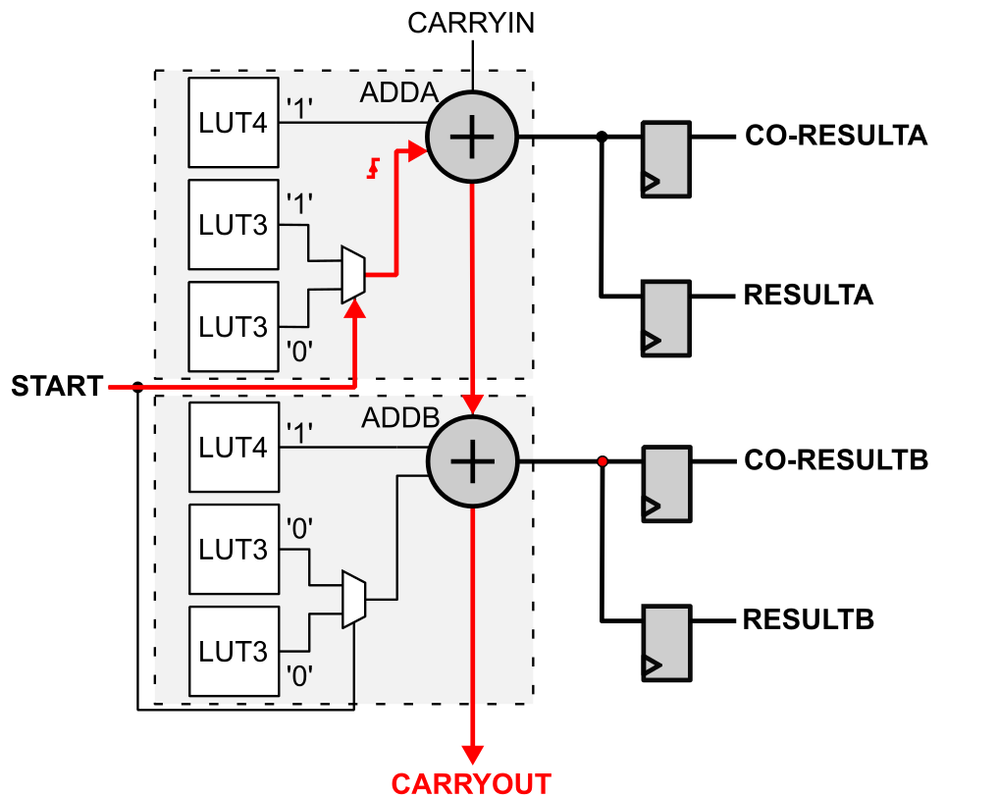
I am trying to implement a time-to-digital converter in Arria 10 FPGA, the schematic of which I have shown in the attached figure. I have many problems with this circuit because of its optimization by Quartus software.
First of all, in HDL I described an adder to perform "0...0"&start + "1...1" operation. To stop the optimization I had to describe the value "1...1" as a signal with the keep attribute. This makes this signal not directly attached to Vcc but is produced by additional ALM blocks, so it increases the consumption of logic resources. Is it possible to fix this? Note that I have already try to use CARRY_SUM primitive, adder IPs and behavioral description, all with the same results.
Next, an even bigger problem is to connect the output of the adder simultaneously to two corresponding flip-flops. According to documentation, it should be possible in ALM arithmetic mode. However, during compilaion additional "feeders" (buffers implemented in look-up tables) are added which cause implementations of the second flip-flop in another ALM block. In the article [Cyclone10_TDC], the authors stated that they achieved this configuration by using two clock inputs to the ALM (e.g. clk(0) for the first flip-flop and clk(1) for the second one), but in my case it didn't work. I also tried various synthesis attributes, but without success.
In a ChipPlanner I was able to manually set ALM for the desired configuration but how can I save this configuration and use in HDL?
Link Copied
- Mark as New
- Bookmark
- Subscribe
- Mute
- Subscribe to RSS Feed
- Permalink
- Report Inappropriate Content
Can you show your code? It's very hard to picture what is going on without seeing how you are attempting to implement this.
- Mark as New
- Bookmark
- Subscribe
- Mute
- Subscribe to RSS Feed
- Permalink
- Report Inappropriate Content
Circuit description in VHDL is attached. In this version flip-flops are randomly implemented using SDATA input (and SLOAD=1) instead of D input. Then no feeder is requried and both flip-flop can be implemented in half-ALM. However, (1) the signal seems to go out of the ALM and get back and (2) flip-flops with SDATA inputs seems to be randomly selected, I do not control this.
- Mark as New
- Bookmark
- Subscribe
- Mute
- Subscribe to RSS Feed
- Permalink
- Report Inappropriate Content
For the optimization issue you can try add 'preserve' attribute to the signal to prevent it from being optimized away.
- Mark as New
- Bookmark
- Subscribe
- Mute
- Subscribe to RSS Feed
- Permalink
- Report Inappropriate Content
Thank you for a hint but I'm using 'keep' attribute to avoid optimization. According to the description in a Quartus template, 'keep' should be used for combinationl circuits and 'preserve' for registers. In my case, I care about preserving the fast carry chain in the adder, so combinational circuit. As noted in my original post, 'keep' attribute indeed allows me to implement this circuit but it also causes additional logic to appear to produce fixed logical values for one of the inputs of the adder.
Overall, I would simply like to get a circuit like the one shown in the Arria 10 documentation describing the ALM arithmetic mode (with two flip-flops connected simultaneously to one output from the adder): https://www.intel.com/content/www/us/en/docs/programmable/683461/current/arithmetic-mode.html.
- Mark as New
- Bookmark
- Subscribe
- Mute
- Subscribe to RSS Feed
- Permalink
- Report Inappropriate Content
Hi there, have you tried logic lock to constrain the two registers to the same ALM. You can get reference from the following link: https://www.intel.com/content/www/us/en/docs/programmable/683230/18-1/creating-regions-with-the-chip-planner.html
- Mark as New
- Bookmark
- Subscribe
- Mute
- Subscribe to RSS Feed
- Permalink
- Report Inappropriate Content
Logic lock didn't help because Quartus thought it needed a larger area to locate the circuit. However, I somehow managed the implementation: instead of DFF primitives, I described the register using a process and manually deployed the elements in Chip Planner. After saving the placement and recompiling, the ALM configuration was as expected. The problem of implementing additional ALMs to set a fixed value of '1...1' on one of the inputs remained, but I can live with that.
- Mark as New
- Bookmark
- Subscribe
- Mute
- Subscribe to RSS Feed
- Permalink
- Report Inappropriate Content
As we do not receive any response from you on the previous question/reply/answer that we have provided. Please login to ‘https://supporttickets.intel.com’, view details of the desire request, and post a feed/response within the next 15 days to allow me to continue to support you. After 15 days, this thread will be transitioned to community support. The community users will be able to help you on your follow-up questions.
- Mark as New
- Bookmark
- Subscribe
- Mute
- Subscribe to RSS Feed
- Permalink
- Report Inappropriate Content
We (Intel) have logged-out from the post as we do not receive any response from you on the previous reply that we have provided. You can “Bring It Back To Our Attention” by logging in here https://supporttickets.intel.com/s/?language=en_US as soon as possible for further support.
- Subscribe to RSS Feed
- Mark Topic as New
- Mark Topic as Read
- Float this Topic for Current User
- Bookmark
- Subscribe
- Printer Friendly Page