- Mark as New
- Bookmark
- Subscribe
- Mute
- Subscribe to RSS Feed
- Permalink
- Report Inappropriate Content
I got a three bit counter module which reset to 3'b000 every sixth count of clock. when I simulated using quartus II 7.2, I found wrong numbers after count values of 1, 3 and 5. (That is simulation showed count=3 after 1, then count correctly moves to 2. Then count becomes 5 after 3, but then moves correctly to 4. And becomes 1 after 5, but then correctly becomes 0.) The image of the simulation is attached along. (I wonder if these are jitters but how can they be jitters during simulation. Am I doing something wrong here? And how can these be removed?)
Here is my code: module test(clk, reset, tstport); input clk,reset; output [2:0] tstport; reg [2:0] cnt; assign tstport=cnt; /* Implementation of testing the counter */ always @(posedge clk or negedge reset) begin if(reset==1'b0) begin cnt=3'b000; end else begin cnt=cnt+3'b001; //useful $0-$5 (needed only six states) if(cnt>3'b101) cnt=3'b000; end end endmodule
Link Copied
- Mark as New
- Bookmark
- Subscribe
- Mute
- Subscribe to RSS Feed
- Permalink
- Report Inappropriate Content
You didn't examine the simulation results thoroughly. Take a look at the individual output bits, then you see, that they always have a correct logic state according to the expected counter value, there are no glitches! The problem is however, that they don't change state exactly at the same time, cause each output has an individual delay.
Quartus performs timing rather than functional simulation by default and takes routing delay into account. As general problem behind the simulation, a binary coded value isn't valid without a clock or a qualifier, that guarantees the value isn't just changing when you watch it. You would need a gray coded counter to overcome this problem. Just an additional remark regarding coding style. Although the used blocking assignment is correct Verilog syntax,cnt=cnt+3'b001; //useful $0-$5 (needed only six states)
if(cnt>3'b101) cnt=3'b000; I would prefer non-blocking assignment to avaoid potentially confusing multiple assignments to cnt. if(cnt>=5) cnt<=3'b000;
else cnt<=cnt+3'b001;
- Mark as New
- Bookmark
- Subscribe
- Mute
- Subscribe to RSS Feed
- Permalink
- Report Inappropriate Content
Thanks for the Info. I just tried with the gray coded counter. (The code is given below). Even this case, there are glitches. This has surprised me since only one line should change in this case. For example, from six->four, transitional values of 4 and 5 are noted. Has this to something to do with capacitances...etc? (Also attached is the image).
Please also note that the timing delays before the state change. Is that because I got the I/O ports of the module left unassigned to real pins of the FPGA (I am using cyclone II 2c35 as my test device). Thanks. Here is my code: module test(clk, reset, tstport); input clk,reset; output [2:0] tstport; reg [2:0] cnt; assign tstport=cnt; always @(posedge clk or negedge reset) begin if(reset==1'b0) begin cnt<=3'b000; end else begin case(cnt) 3'b000: cnt<=3'b001; 3'b001: cnt<=3'b011; 3'b011: cnt<=3'b010; 3'b010: cnt<=3'b110; 3'b110: cnt<=3'b100; 3'b100: cnt<=3'b000; 3'b101: cnt<=3'b000; 3'b111: cnt<=3'b000; default: cnt<=3'b000; endcase end end endmodule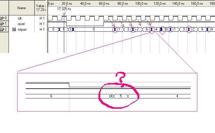
- Mark as New
- Bookmark
- Subscribe
- Mute
- Subscribe to RSS Feed
- Permalink
- Report Inappropriate Content
Surprizing result :D
This is, cause Quartus integrated synthesis is too clever in this case. It infers a state machine (with different coding), where no state machine is intended. See quartus handbook, vol 1, sect. iii.8 quartus ii integrated synthesis, quartus ii synthesis options, preserve registers Knowing the problem, you can manage it easily:reg cnt /* synthesis syn_preserve = 1 */;
- Mark as New
- Bookmark
- Subscribe
- Mute
- Subscribe to RSS Feed
- Permalink
- Report Inappropriate Content
:confused:
--- Quote Start --- ....Quartus integrated synthesis is too clever in this case --- Quote End --- too clever or clever enough? Is this a desired feature? Thanks- Mark as New
- Bookmark
- Subscribe
- Mute
- Subscribe to RSS Feed
- Permalink
- Report Inappropriate Content
If you bring the count value to output ports, i.e. if you need those exact values, then it will synthesize to what you want. Otherwise, internally it is synthesizing to what is generally the best result. Generally the only reason to use a gray-code counter is to cross clock-domains(and therefore remove the glitches). But otherwise you want what the original binary code. EVERYTHING has different delays in a device, so when you look at multiple signals as a group, they will always look like they're glitching to a different value. That is what static timing analysis does, is it basically determines that your transitiions occur between clock edges, and when the clock samples a state, all the signals are not transitioning and are at the correct state. In your original attachment where you show the "wrong state", it is not what you want, but since you're not using the value of count until the next clock edge, these glitched have filtered out. (Unless you're crossing asynchronous domains). So your code was fine without doing a gray-code.
- Subscribe to RSS Feed
- Mark Topic as New
- Mark Topic as Read
- Float this Topic for Current User
- Bookmark
- Subscribe
- Printer Friendly Page