- Mark as New
- Bookmark
- Subscribe
- Mute
- Subscribe to RSS Feed
- Permalink
- Report Inappropriate Content
Link Copied
- Mark as New
- Bookmark
- Subscribe
- Mute
- Subscribe to RSS Feed
- Permalink
- Report Inappropriate Content
I understand, that you want to operate the Pluto-II board (a small Cyclone EP1C3 dev kit from KNJN.com) as an ethernet transceiver without a PHY, by directly connecting the ethernet magnetic to FPGA pins? Can you refer to an existing application?
In my opinion, it can possibly work for 10BASE-T, using a LVDS receiver for RX. But you would at least need to bias the receiver to 1.2V and should provide 100 ohm differential termination for Rx and Tx. Also the a 10BASE-T filter should be used for the magnetics rather than a 100BASE-TX transformer only.- Mark as New
- Bookmark
- Subscribe
- Mute
- Subscribe to RSS Feed
- Permalink
- Report Inappropriate Content
Yes the application is as shown in the photo.
Mic - Preamp - Delta Sigma Modulator - Decimation Filter - Udp transmitter ONLY with 512 bytes payload and transmitting 305 pps ( 3.3ms interframe gap ). Everything works great as i checked but only the PC doesnt receive packets. I scope the Tx pins to trace the packets and i did. Maybe i did a mistake on the Pulse RJ45 and connecting only a cap 100nF to the pin_4 of its transformer. So you are telling me that i have to add also a RC filter? 100Ohm and a cap(value?)? The project is done by me and refugee in IPL in Portugal as Erasmus Students. http://i252.photobucket.com/albums/hh3/unoturbomk2/Image009.jpg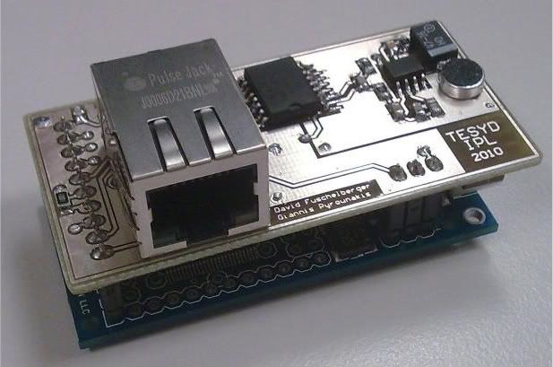
- Mark as New
- Bookmark
- Subscribe
- Mute
- Subscribe to RSS Feed
- Permalink
- Report Inappropriate Content
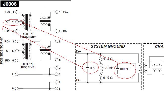
O.K., transmit only should be more easy. But without knowing how the connected pins are driven logically, I can't determine if something wrong with the circuit. I know Tx circuits of regular 10BASE-T PHYs, that also drive basically logic levels to the magnetics. They won't work correctly with a capacitor connected to the center tap, because it disturbs the output signal. The chip is e.g. driving "11" in idle state and "01" or "10" for positive or negative signal. To give correct output levels, the center tap must be allowed to float in this case. But your drive scheme is possibly different. I don't understand the purpose of the RL termination, that differs from usual ethernet circuits.
Of course, the problem may be caused by higher ethernet protocol layers as well. Before receiving packets, the peer (PC) should be able to detect a link. But the best way is to check the generated output with an oscilloscope against ethernet signal specification. You said, you have watched the signal, you should try to find out if the waveform is correct.- Mark as New
- Bookmark
- Subscribe
- Mute
- Subscribe to RSS Feed
- Permalink
- Report Inappropriate Content
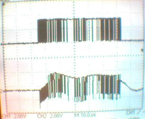
I scope the packet after the Pulse RJ45 (Magnetics ).
I am not so experienced but can you see the preable (is e little weird)? Better Figure on the next post (sorry)- Mark as New
- Bookmark
- Subscribe
- Mute
- Subscribe to RSS Feed
- Permalink
- Report Inappropriate Content
Here is the Tx + and - after the RJ45 tested on cable.
http://i252.photobucket.com/albums/hh3/unoturbomk2/PlusMInusTX.jpg And here is the comparison between before RJ45 (magnetics) and after on the Cable of one of the Tx wires. http://i252.photobucket.com/albums/hh3/unoturbomk2/Beforeandafter.jpg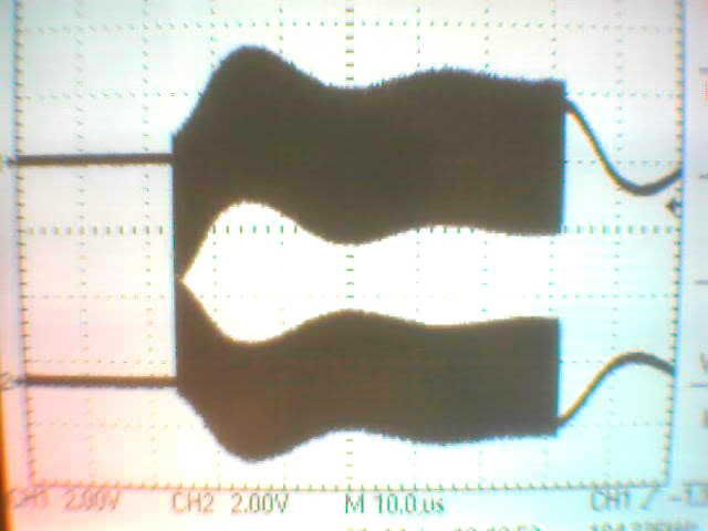
- Mark as New
- Bookmark
- Subscribe
- Mute
- Subscribe to RSS Feed
- Permalink
- Report Inappropriate Content
- The slow oscillation shouldn't be present. It's caused by the 100 nF capacitor I fear. Simply try to omit it.
- The waveform looks not exactly as specified by the IEEE 802.3, Section 1, Clause 14 "Twisted-pair medium attachment unit (MAU) and baseband medium, type 10BASE-T". It basically misses the low-pass filter. Practically, this doesn't matter, because the peer will filter signal before processing it. By the way, do you also generate a link test pulse? I'm not sure, if some receivers possibly require it.- Mark as New
- Bookmark
- Subscribe
- Mute
- Subscribe to RSS Feed
- Permalink
- Report Inappropriate Content
Yes i generate a TP_IDLE to notify that i am transmitting SILENCE at the end of every packet for 3bit period (6 CLK Cycles).
So i wont use a cap on the transformer? I remind you that i have only one of 100nF on the transmformer and not on th Tx+ and Tx-. Thank you for the reference.- Mark as New
- Bookmark
- Subscribe
- Mute
- Subscribe to RSS Feed
- Permalink
- Report Inappropriate Content
I don't claim to solve your problem from a distance, particularly as you didn't give much details on the pulse scheme and I/O settings at the FPGA side. But I simply assume, that you are using double push-pull drivers with a scheme as sketched above. Then, as said, "the center tap must be allowed to float". It's the same with integrated PHY controller chips like Davicom DM9008, they are known to fail in operation, if you connect a capacitor at the Tx center tap. True differential current source drivers in contrast have no problem with bypassing the center tap, or even require it.
- Mark as New
- Bookmark
- Subscribe
- Mute
- Subscribe to RSS Feed
- Permalink
- Report Inappropriate Content
First, i am not using the circuit i sketched above, i have only a Cap 100nF on the transformer PIN 4 (in the middle of the transformer) with out this the Tx+ and Tx- after the magnetics are equal.
Second, I am using the exact code of the fpga4fun.com which is tested from many users, so its not a fpga problem, its on the transmittion and probably i have done some mistake on my pcb and the ethernet packets can be received from the PC. Thank you for your interest once more you give me your lights :) If you can help me further it will be appreciated. Giannis- Subscribe to RSS Feed
- Mark Topic as New
- Mark Topic as Read
- Float this Topic for Current User
- Bookmark
- Subscribe
- Printer Friendly Page