- Mark as New
- Bookmark
- Subscribe
- Mute
- Subscribe to RSS Feed
- Permalink
- Report Inappropriate Content
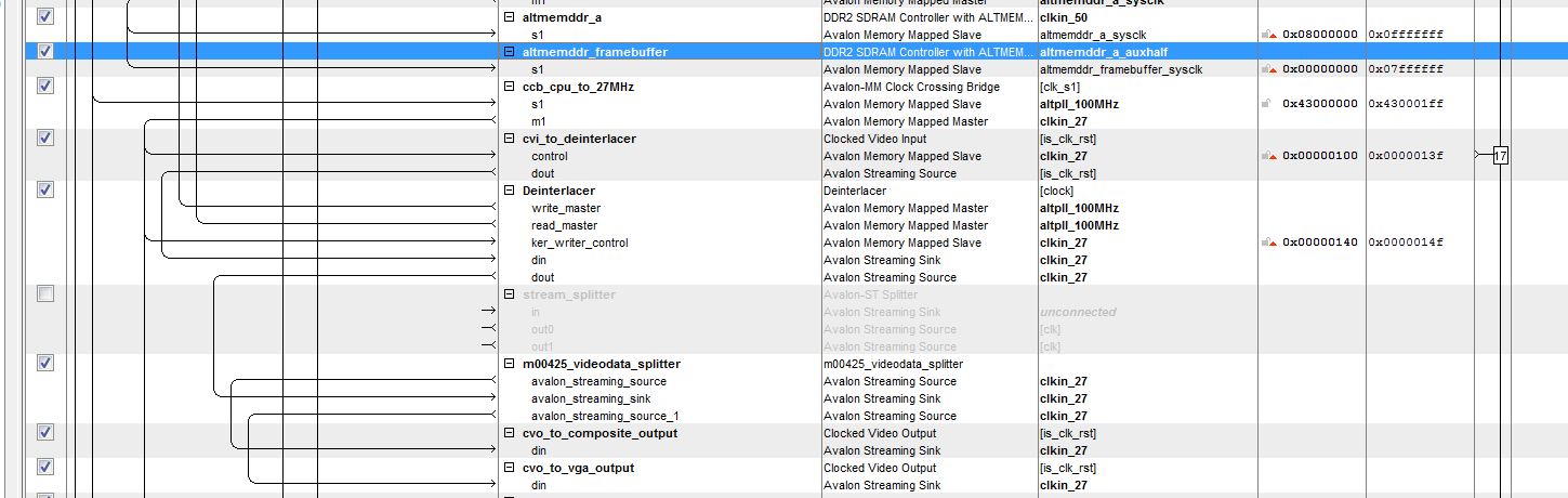
We use 2 frame buffer IPs in our design.
1- The first frame buffer: takes its data (din) from DVI Input IP (VGA_IN_INST) and writes this data into an SDRAM through the SDRAM controller. We do not use the read & dout of this Frame buffer . So, these unused interfaces are connected to an empty dummy component (reference to the service request no. 10773449 ) 2- The second frame buffer: should read the data written by the first Frame buffer in the used SDRAM and gives this data to the DVI out IP (VGA_out_INST). W e do not use the write & din of this Frame buffer. So; these unused interfaces are connected to the same dummy component. Taking into consideration that, the dummy component interfaces are Avalon. Kindly advise about the following 1- Is it applicable to use a Frame buffer to write data in SDRAM and another Frame buffer to read this data from the same SDRAM as described above? 2- How to make sure that the second frame buffer reads the data from the same addresses used by the first frame buffer for writing in the SDRAM? This question is because the addresses are nit indicated when we instantiated the frame buffer in SOPC builderLink Copied
- « Previous
-
- 1
- 2
- Next »
28 Replies
- Mark as New
- Bookmark
- Subscribe
- Mute
- Subscribe to RSS Feed
- Permalink
- Report Inappropriate Content
--- Quote Start --- I'm not an expert in SOPC nor ST designs, as I had developed my own streaming interconnection, which I rather call dataflow interconnection, before looking into Altera's solution. However I looked up the ST- pin connections: It looks to me that you have instantiated the de-interlacer with a 0 width for the empty signal, and so you must instantiate the splitter wit a 0-width empty signal as well. --- Quote End --- Thank you for your reply. When instantiating the de-interlacer in my SOPC design I don't see any option that would let med deside the width of the empty signal. When instantiating the splitter, there are several avalon-st interface signals that can be selected/deselected, however the empty signal is not listed. Is there another way to specify that I wan't to instantiate the splitter with an empty signal of 0 width ? regards
- Mark as New
- Bookmark
- Subscribe
- Mute
- Subscribe to RSS Feed
- Permalink
- Report Inappropriate Content
Like I mentioned, I don't do much SOPC - designs, in fact I just dabbled a bit with it to find out out whether I could coerce/fit my interconnection scheme into an ST-compatible form which surprisingly worked out fine. But I haven't done a real SOPC-project yet.
I found the following in the Quartus II Handbook: Chapter 22: Avalon-ST Splitter Core --- Quote Start --- Error Width : legal values 0–31 : Default 1 : The width of the error signal on the output interfaces. A value of 0 indicates that the error signal is not used. This parameter is disabled when Use Error is set to 0. --- Quote End ---- Mark as New
- Bookmark
- Subscribe
- Mute
- Subscribe to RSS Feed
- Permalink
- Report Inappropriate Content
I think that most SOPC components automatically fix the width of the empty signal depending on the number of symbols per bit that you set up.
Check that the two blocks you connect are set up with the same symbol width and the same number of symbols per beat.- Mark as New
- Bookmark
- Subscribe
- Mute
- Subscribe to RSS Feed
- Permalink
- Report Inappropriate Content
--- Quote Start --- I think that most SOPC components automatically fix the width of the empty signal depending on the number of symbols per bit that you set up. Check that the two blocks you connect are set up with the same symbol width and the same number of symbols per beat. --- Quote End --- Hi and thank you for your reply, When instantiating the Splitter core I have the option to set BITS_PER_SYMBOL and this parameter is set to 8. When instantiating the Deinterlacer I set Bits_per_pixel_per_color_plane to 8, so the bits per symbol should match up between the two blocks. However, the error message continues to appear. (See attached files). In the video and image processing suite (w)ww.altera.com/literature/ug/ug_vip.pdf I found that the SYMBOLS_PER_BEAT is always equal to the number of color samples being transferred in parallel. From this I can see that I'm using one symbol per beat as I'm using a single color plane(B/W). Also, I found from the avalon interface spesification (w)ww.altera.com/literature/manual/mnl_avalon_spec.pdf that the empty signal is not used on interfaces where there is one symbol per beat. So now I'm wondering why the splitter is still requesting the use of the empty signal ? regards
- Mark as New
- Bookmark
- Subscribe
- Mute
- Subscribe to RSS Feed
- Permalink
- Report Inappropriate Content
--- Quote Start --- I think you'll have to make a custom component for that, with one sink and two sources. Just connect all the signals from the sink to both sources, and for the 'ready' signal, do an 'and' between the signals from the two sources and put the result on the sink. I think it should work. Depending on what you connect your component to, you may need to put some FIFOs to handle the cases when your two IPs aren't ready at the same time. --- Quote End --- Hi again, I have another question. For the timebeing I'w placed a custom splitter between the deinterlacer and two clocked video outs. For the 'ready' signal of the two clocked video outputs I'm using 'and' in order to provide it to the deinterlacer 'dout' source. The clocked video outputs are driven by a 27MHz clock in the SOPC design, however they are using different clocking clocks, one is operating at 27MHz(NTSC) and one at 40MHz(VGA). The framerate for both output formats is at 60Hz. As of now, I haven't tryed clocking the frames out to screen (just got my hardware), but will this setup work properly or could there be issues with regard to the different video output clocks ?
- Mark as New
- Bookmark
- Subscribe
- Mute
- Subscribe to RSS Feed
- Permalink
- Report Inappropriate Content
I'm guessing that you'll have to run everything at 40Mhz when doing the VGA output. You need a higher pixel clock than with the NTSC output.
- Mark as New
- Bookmark
- Subscribe
- Mute
- Subscribe to RSS Feed
- Permalink
- Report Inappropriate Content
--- Quote Start --- Originally Posted by Daixiwen I think you'll have to make a custom component for that, with one sink and two sources. Just connect all the signals from the sink to both sources, and for the 'ready' signal, do an 'and' between the signals from the two sources and put the result on the sink. I think it should work. Depending on what you connect your component to, you may need to put some FIFOs to handle the cases when your two IPs aren't ready at the same time. --- Quote End --- A simple and won't do. You have to and the output flag of the source with the and of the the output flags from the sinks before feeding the input flags of the sinks.
ready_source <= ready_sink0 and ready_sink1 ;
valid_sink0 <= valid_source and ready_source ;
valid_sink1 <= valid_source and ready_source ;
This will stall the source until both sinks are ready to accept a transfer. --- Quote Start --- I'm guessing that you'll have to run everything at 40Mhz when doing the VGA output. You need a higher pixel clock than with the NTSC output. --- Quote End --- You can add a clock-domain-xing fifo (= dcfifo) on one of the outputs of your custom splitter and thus run the 2 chains at their original frequency. It seems that the 40 MHz chain is the one where you could best place the dcfifo. Although I thought I read somewhere that SOPC inserts rate converters (Timing Adaptor) automatically -> page 3.3 of the Quartus Handbook says: --- Quote Start --- The insert avalon-st adapters command on the System menu attempts to correct these errors automatically, if possible, by inserting the appropriate adapter types. --- Quote End ---
- Mark as New
- Bookmark
- Subscribe
- Mute
- Subscribe to RSS Feed
- Permalink
- Report Inappropriate Content
--- Quote Start --- A simple and won't do. You have to and the output flag of the source with the and of the the output flags from the sinks before feeding the input flags of the sinks.
ready_source <= ready_sink0 and ready_sink1 ;
valid_sink0 <= valid_source and ready_source ;
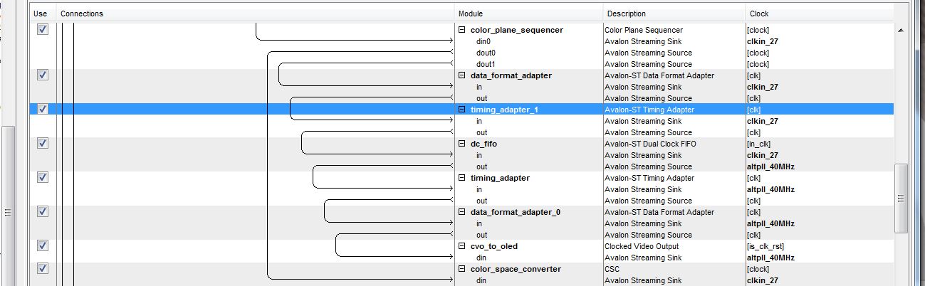
valid_sink1 <= valid_source and ready_source ; This will stall the source until both sinks are ready to accept a transfer. --- Quote End --- It's possible to use the "color plane sequencer" inorder to splitt up a single input stream into two separate output streams. --- Quote Start --- You can add a clock-domain-xing fifo (= dcfifo) on one of the outputs of your custom splitter and thus run the 2 chains at their original frequency. It seems that the 40 MHz chain is the one where you could best place the dcfifo. Although I thought I read somewhere that SOPC inserts rate converters (Timing Adaptor) automatically -> page 3.3 of the Quartus Handbook says: --- Quote End --- When adding an dc_fifo at the dout1 of the "color plane sequencer" I encountered some compatibility issues between the avalon-st interface and the avalon-st video interface. It seems that the avalon-st video interface doesnt support the "empty" signal and also the ready latency was different for the dc_fifo and the "color plane sequencer. In order to solve the "empty" signal issue an "data format adapter" was placed before and after the dc_fifo. To solve the latency issue an "timing adapter" was placed before and after the dc_fifo.
Reply
Topic Options
- Subscribe to RSS Feed
- Mark Topic as New
- Mark Topic as Read
- Float this Topic for Current User
- Bookmark
- Subscribe
- Printer Friendly Page
- « Previous
-
- 1
- 2
- Next »