- Mark as New
- Bookmark
- Subscribe
- Mute
- Subscribe to RSS Feed
- Permalink
- Report Inappropriate Content
Hello, I want to implement sine and cosine signals in vhdl to check a part of my code but i don't know how to initialize these sin and cos signals? please tell me what is the way to do it?
i have read that it is possible through LUT but i don't know what LUT is ???Link Copied
- Mark as New
- Bookmark
- Subscribe
- Mute
- Subscribe to RSS Feed
- Permalink
- Report Inappropriate Content
A lut is a ROM containing all of the Sin Values - so for a table of sin(x) - x is the address to the ROM.
- Mark as New
- Bookmark
- Subscribe
- Mute
- Subscribe to RSS Feed
- Permalink
- Report Inappropriate Content
Hi! I have the same project.I want to create sin-signal for tests, but it's an error when I put negative numbers into .mif file. Insted of negative numbers Questa show me zeros.
How Can I solve this problem? Main code:
module single_rom
		(
			addr,
			clk,
			q
		);


	//input
	input  addr ;
	input clk;
	output signed  q;


	//ip-cores
	rom_ip	rom_ip_component (
				.address (addr),
				.clock (clk),
				.q (q));


endmodule
Testbench:
`timescale 1 ps/ 1 ps
module single_rom_tb();

// test vector input registers
reg  addr;
reg clk;
// wires
wire signed   q;
// assign statements (if any)
single_rom i1 (
// port map - connection between master ports and signals/registers
	.addr(addr),
	.clk(clk),
	.q(q)
);
//clk
initial
		begin
		  clk = 0;
		  forever# 10 clk = ~clk;
		end
//beginning address
initial
			addr = 7'h00;
//loop
always
	begin
		@(posedge clk)
		if (addr >= 7'h64)
			addr = 7'h0;
		else
			addr = addr + 7'h1;
	end

endmodule
Contents of .mif file:
WIDTH=16;
DEPTH=110;
ADDRESS_RADIX=UNS;
DATA_RADIX=DEC;
CONTENT BEGIN
	0    :   0;
	1    :   5;
	2    :   15;
	3    :   80;
	4    :   345;
	5    :   656;
	6    :   -1;
	7    :   -2;
	8    :   -3;
	9    :   -4;
	10   :   -5;
	11   :   -6;
	12   :   20886;
	13   :   22430;
	14   :   23885;
	15   :   25247;
	16   :   26508;
	17   :   27665;
	18   :   28713;
	19   :   29648;
	20   :   30465;
etc
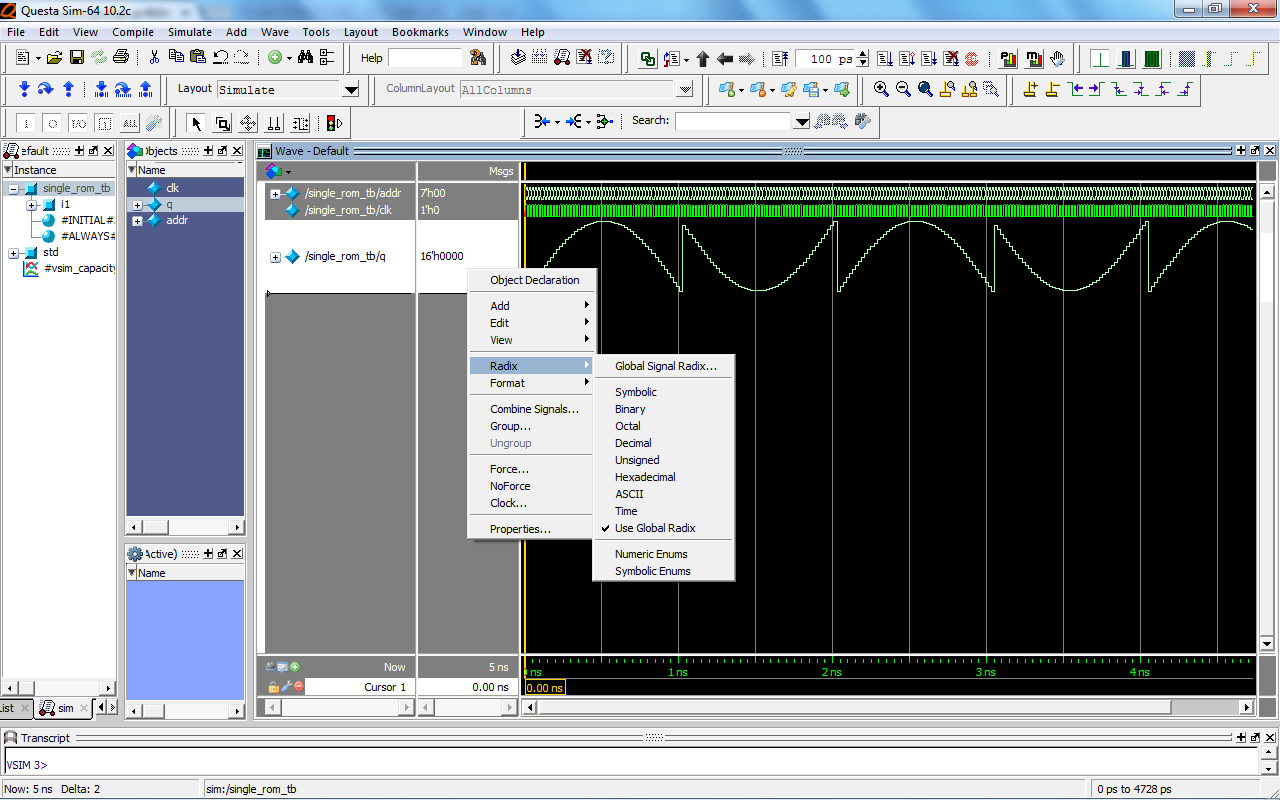
Picture, you can see zeros instead of negative numbers: http://s7.hostingkartinok.com/uploads/thumbs/2014/11/03327b0a1b3e6e4dc3e1dd541e47935d.png (http://hostingkartinok.com/show-image.php?id=03327b0a1b3e6e4dc3e1dd541e47935d)
- Mark as New
- Bookmark
- Subscribe
- Mute
- Subscribe to RSS Feed
- Permalink
- Report Inappropriate Content
I don't about your tools habits but you can convert negative numbers to positive (bit equivalent):
e.g. for n bits negative values (signed) data = data + 2^n- Mark as New
- Bookmark
- Subscribe
- Mute
- Subscribe to RSS Feed
- Permalink
- Report Inappropriate Content
--- Quote Start --- I don't about your tools habits but you can convert negative numbers to positive (bit equivalent): e.g. for n bits negative values (signed) data = data + 2^n --- Quote End --- Thank's for your answer, but I did it and I got the following picture it Questa. I can't submit it like a signed number. In radix I use decimal, but it also ansigned. How can i transform it into unsigned? http://s7.hostingkartinok.com/uploads/images/2014/11/504de2f5c58eae37f09eb5c10191f761.png (http://hostingkartinok.com/show-image.php?id=504de2f5c58eae37f09eb5c10191f761)
- Mark as New
- Bookmark
- Subscribe
- Mute
- Subscribe to RSS Feed
- Permalink
- Report Inappropriate Content
Not sure if this will fix your problem, but try replacing the "signed" declarations with "integer" in your main code and testbench.
- Mark as New
- Bookmark
- Subscribe
- Mute
- Subscribe to RSS Feed
- Permalink
- Report Inappropriate Content
I did it, but it didn't fix my problem.
http://s7.hostingkartinok.com/uploads/images/2014/11/c82d65b2ad13d7b4b3412aaadc4a4fce.png (http://hostingkartinok.com/show-image.php?id=c82d65b2ad13d7b4b3412aaadc4a4fce)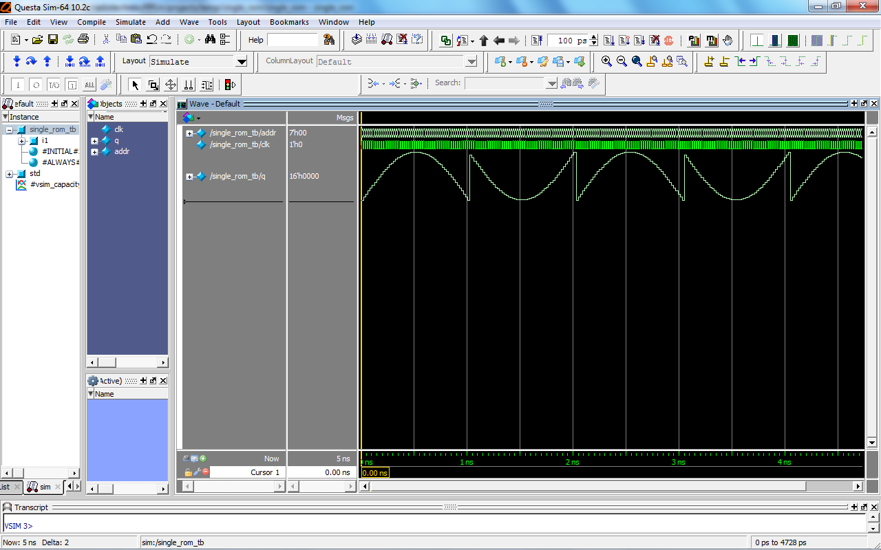
- Mark as New
- Bookmark
- Subscribe
- Mute
- Subscribe to RSS Feed
- Permalink
- Report Inappropriate Content
sorry, can you show me how to do it, i don't understand.
- Mark as New
- Bookmark
- Subscribe
- Mute
- Subscribe to RSS Feed
- Permalink
- Report Inappropriate Content
You are displaying the wave form as hexadecimal. Change the draw type to "signed". Right click -> radix -> signed
- Mark as New
- Bookmark
- Subscribe
- Mute
- Subscribe to RSS Feed
- Permalink
- Report Inappropriate Content
no changes, yesterday I wrote about it, but massage didn't post.
I also try -radix signal q signed.- Mark as New
- Bookmark
- Subscribe
- Mute
- Subscribe to RSS Feed
- Permalink
- Report Inappropriate Content
I want to create a sin, so the best way (as I understand) is to make nco (I need digital sin-wave). Please, can you advice me some examples about implementation nco in verilog.
- Mark as New
- Bookmark
- Subscribe
- Mute
- Subscribe to RSS Feed
- Permalink
- Report Inappropriate Content
The wave screenshot posted above already shows a different problem than what you have reported initially. The negative values are not replaced with zeros anymore, rather you seem to be missing the sign bit this time. You need to inspect the values shown in the diagram to be able to tell what's happening - for example, what is the value at the peak of the sinusoid? For 16bit signed integer, your values in the LUT/MIF should be in the [-32768;+32767] interval, are they?
- Mark as New
- Bookmark
- Subscribe
- Mute
- Subscribe to RSS Feed
- Permalink
- Report Inappropriate Content
--- Quote Start --- I did it, but it didn't fix my problem. --- Quote End --- your mif file is set to unsigned radix but the data ia signed so keep it signed and change radix in mif file to signed
- Subscribe to RSS Feed
- Mark Topic as New
- Mark Topic as Read
- Float this Topic for Current User
- Bookmark
- Subscribe
- Printer Friendly Page