- Mark as New
- Bookmark
- Subscribe
- Mute
- Subscribe to RSS Feed
- Permalink
- Report Inappropriate Content
Hello everybody,
I would like to connect the RGMII ethernet phy to Max10 device. The phy can output clock and data at 25MHz or 125 MHz (depending in the ethernet datarate), and i would like that my design runs at constant frequency.
Is there a way to achieve that with a single PLL avaliable in Max10 device.
Q1: Can i set constraints and the PLL to 125 MHz and assume the design will run also at 25MHz?
Q2: Is there a way to configure the output PLL clock to run at constant frequency. If i want the clock freq. to be set to consctant 125MHz, can i set the C0 to multiply frequency by 1 and C1 to multiply by 5 and than switch between those two outputs depending on the input frequency?
Regards
Link Copied
- Mark as New
- Bookmark
- Subscribe
- Mute
- Subscribe to RSS Feed
- Permalink
- Report Inappropriate Content
Hi,
https://www.intel.com/content/dam/www/programmable/us/en/pdfs/literature/hb/max-10/ug_m10_clkpll.pdf
as per above link, 2.3.12. Clock Switchover chapter talks about changing the input reference clock frequency (only 2 frequencies)
apart from that, you can use Asynchronous FIFO to work in a constant frequency.
In Asynchronous FIFO,
on the transmission side, write the data to Asynchronous FIFO with the constant frequency and Ethernet interface may read this data wrt the link clock and take it to next level. Otherway, in the receiver side.
With Regards,
HPB
- Mark as New
- Bookmark
- Subscribe
- Mute
- Subscribe to RSS Feed
- Permalink
- Report Inappropriate Content
Thank you for your suggestion.
I tried to implement this for 125/25MHz, but the ALTPLL Wizard "Cannot implement the requested PLL. Cause: VSO or PFD frequency range exceeded". Also it cannot implement the parameters shown in the example on page 30: "For example, if inclk0 is 66 MHz and inclk1 is 200 MHz, you must control theswitchover using the clkswitch signal. The automatic clock sense circuitry cannotmonitor clock input (inclk0 and inclk1) frequencies with a frequency difference ofmore than 20%." Any idea why? I have the manual switch selected.
Asynchronous FIFO would be used for clock domain crossing. But still i have no idea how to generate a constant frequency with single PLL with variable (25/125MHz) input frequency. Can i also make a swith on the output clock - but then it would be a problem because i have to specify the c0 clock for compensation?
Regard
- Mark as New
- Bookmark
- Subscribe
- Mute
- Subscribe to RSS Feed
- Permalink
- Report Inappropriate Content
Hi,
At the moment, I am unable to give suggestion on 125/25MH input to ALTPLL. There may some relation/constraint for switchable input frequency range specified .
Regarding Async FIFO, I hope the FPGA platform which you are using is having atleast one more system clock other than clocks generated by RGMII.
Use that system clock to generate the clock with constant frequency. So, RGMII clocks & system clock will be the 2 asynchronous clocks in your design.
With regards,
HPB
- Mark as New
- Bookmark
- Subscribe
- Mute
- Subscribe to RSS Feed
- Permalink
- Report Inappropriate Content
Thank you for your reply.
There is a constant 125MHz clock source available, but the problem is that the Max10 in U169 package has only one PLL, so i cannot use two clock sources ...or is there a way to clock the system with a second clock source without the PLL?
So the only option would be is to have two designs (one for 25MHz clock and the other for 125Mhz clock) stored in configuration flash and a watchdog to switch between them?
- Mark as New
- Bookmark
- Subscribe
- Mute
- Subscribe to RSS Feed
- Permalink
- Report Inappropriate Content
Hi,
There is a constant 125MHz clock source available.
You can use this clock as the constant clock. You don't need PLL to use this clock. PLL is required only when we need to have some clock synthesis / derive different frequency. otherwise, we can directly use the clock in our design.
Just define 125MHz as the system clock pin in qsf file and define the frequency of the clock in .sdc file.
FYI U169 package allows around 4 single ended clocks as it has 4 pairs of clock capable pins ( CLK0p/n, CLK1p/n, CLK2p/n, CLK3p/n) but only one PLL. The 125MHz must be connected any one of the clock capable pins of FPGA so that compilation will not give any error/warning.
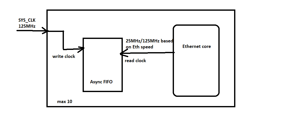
Just a block representation is attached. It shows how we can work with a constant clock freq. using Async FIFO. This is for transmission side. On the receiver side, we need to have one more Async fifo with swapped read & write clock.
With regards,
HPB
- Mark as New
- Bookmark
- Subscribe
- Mute
- Subscribe to RSS Feed
- Permalink
- Report Inappropriate Content
Great, thank you for your suggestion, this seems feasible :)
Just one more question: it may turn out that the constant 125MHz clock is a bit too high for my design. Is there a simple way to divide it without the PLL or should i drive the clock signal through some external discrete flipflop on the pcb?
Regards
- Mark as New
- Bookmark
- Subscribe
- Mute
- Subscribe to RSS Feed
- Permalink
- Report Inappropriate Content
Hi,
If at all the available PLL is not at all used in your design, you can use it to generate lower frequency from 125MHz system clock.
Otherwise, the idea is to try to use counter logic to divide the clock and see whether it will work or not. I am not sure whether any issue ( compilation warnings/errors) will appear when we use counter to derive the clock.
With Regards,
HPB
- Mark as New
- Bookmark
- Subscribe
- Mute
- Subscribe to RSS Feed
- Permalink
- Report Inappropriate Content
Thank you very much for your help :)
- Mark as New
- Bookmark
- Subscribe
- Mute
- Subscribe to RSS Feed
- Permalink
- Report Inappropriate Content
This thread will be transitioned to community support. If you have a new question, feel free to open a new thread to get the support from Intel experts. Otherwise, the community users will continue to help you on this thread. Thank you
- Subscribe to RSS Feed
- Mark Topic as New
- Mark Topic as Read
- Float this Topic for Current User
- Bookmark
- Subscribe
- Printer Friendly Page