- Mark as New
- Bookmark
- Subscribe
- Mute
- Subscribe to RSS Feed
- Permalink
- Report Inappropriate Content
Hi ,
I am trying to bring up a new Apollo Lake-based platform with a coreboot+SeaBIOS combination - it is very similar to the Leaf Hill CRB so I adapted my platform code using the Leaf Hill project as base. I stitched the coreboot outputs into an IFWI as instructed by the Apollo_Lake_Coreboot_MR1_Release_Notes.pdf. I ran the resulting output binary on an Leaf Hill CRB, and the binary runs successfully up until RAM initialization phase where it stops (due differences in board ID and RAM type, so this stop is expected, point being it looks like the binary works as expected).
However, when I try to run the binary on my brand new platform, which is programmed for the first time ever, then I can see using an oscilloscope that the binary's flash descriptor section is read (the first 332 bytes of the binary, as this is the length of the descriptor's content). Thereafter all SPI transactions stop. See below flash map:
Start (hex) End (hex) Length (hex) Area Name
----------- --------- ------------ ---------
00000000 007FFFFF 00800000 Full Flash Image
00000014 00000017 00000004 FLMAP0 - Flash Map 0 Register
00000018 0000001B 00000004 FLMAP1 - Flash Map 1 Register
0000001C 0000001F 00000004 FLMAP2 - Flash Map 2 Register
00000030 0000003B 0000000C FCBA - Flash Component Registers
00000040 00000043 00000004 FLREG0 - Flash Region 0 (Flash Descriptor) Register
00000044 00000047 00000004 FLREG1 - Flash Region 1 (IFWI) Register
00000048 0000004B 00000004 FLREG2 - Flash Region 2 (Intel(R) TXE) Register
00000050 00000053 00000004 FLREG4 - Flash Region 4 (Platform Data) Register
00000054 00000057 00000004 FLREG5 - Flash Region 5 (Device Expansion) Register
00000060 00000063 00000004 FLREG8 - Flash Region 8 (Embedded Controller) Register
00000080 00000083 00000004 FLMSTR1 - Flash Master 1 (Host CPU/BIOS)
00000084 00000087 00000004 FLMSTR2 - Flash Master 2 (Intel(R) TXE)
00000100 000002FF 00000200 FPSBA - SoC Straps (Including Padding)
00000DF0 00000EFF 00000110 VSCC Table
00000DF0 00000DF7 00000008 W25Q128FW
00000DF8 00000DFF 00000008 ATF26DF321
00000E00 00000E07 00000008 N25Q128
00000E08 00000E0F 00000008 N25Q064
00000E10 00000E17 00000008 MT25QU128ABA
00001000 0037FFFF 0037F000 Boot Partition 1
00001000 000F9FFF 000F9000 Primary Boot Partition
00001200 0000120F 00000010 IFP Overrides Partition
00001210 00001317 00000108 Unified Emulation Partition (UEP)
00002000 00004FFF 00003000 OEM SMIP Partition
00005000 0000EFFF 0000A000 CSE RBE Partition
0000F000 0001EFFF 00010000 PMCP
0001F000 0007AFFF 0005C000 CSE BUP Partition
0007B000 0007EFFF 00004000 uCode Partition
0007B040 0007EC3F 00003C00 uCode Patch 1
0007F000 000F7FFF 00079000 IBB Partition
000F8000 000F9FFF 00002000 Debug Token Partition
000FA000 00200FFF 00107000 Secondary Boot Partition
000FA200 00200FFF 00106E00 CSE Main Partition
00380000 006FEFFF 0037F000 Boot Partition 2
00380000 003801FF 00000200 Primary Boot Partition
00380200 00481FFF 00101E00 Secondary Boot Partition
00381000 00481FFF 00101000 OBB Partition
006FF000 007FEFFF 00100000 TXE Data Region
I suspect this is because the TXE bypass ROM has not been programmed yet, but I do not know how to do this. I tried to simply program the "cse_image.bin" that accompanied the FIT tool I am using to stitch with, onto the flash device and then cycle power on the board, but during power-on SPI transactions stops right after the flash descriptor's signature (at address 0x10) is read. Then I reloaded my original IFWI binary and ran it, but there's no difference to previous attempts.
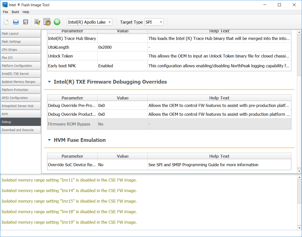
I also tried to enable the "Firmware ROM Bypass" setting in FIT tool but this option is grayed out in the FIT tool and cannot be selected - please see attached screen shot. (Also tried enabling it in the XML file used by FIT, and in a next attempt tried to manually set the corresponding bit in the final binary itself, but no success).
Please can you maybe point me to instructions that explain how to program brand new hardware for the first time after the hardware is produced? Or can you please maybe tell me what I am doing wrong? Do I need to strap any resistors for the bring-up (that differs from recommended operational strapping)? Been struggling for some time and have no idea how to go forward!
Best regards,
Link Copied
- Mark as New
- Bookmark
- Subscribe
- Mute
- Subscribe to RSS Feed
- Permalink
- Report Inappropriate Content
- Mark as New
- Bookmark
- Subscribe
- Mute
- Subscribe to RSS Feed
- Permalink
- Report Inappropriate Content
Hello, Tahnia :
Thank for contacting Intel Embedded Community.
In order to be on the same page, could you please tell us if the affected is a third-party design or it has been developed by you? In case that it is a third-party device, could you please give us all the information related to it?
Wating for your reply.
Best regards,
Carlos_A.
- Mark as New
- Bookmark
- Subscribe
- Mute
- Subscribe to RSS Feed
- Permalink
- Report Inappropriate Content
Hi Carlos,
The platform was developed in-house, and the schematics and PCB layout have been reviewed by Intel. Some component information:
- SoC, E3900 series, E-0 stepping
- IDT P91E0-i5 PMIC
- Micron MT25QU128ABA SPI Flash, where the BIOS image is stored
- An Intel MAX10 FPGA, which among other things is used to multiplex SPI access to the boot flash between the programmer and the SoC.
Please let me know if you require any other information.
Best regards,
Tahnia
- Mark as New
- Bookmark
- Subscribe
- Mute
- Subscribe to RSS Feed
- Permalink
- Report Inappropriate Content
Hello, Tahnia :
Thanks for your reply.
In order to help you as a reference please address your consultations related to SeaBios to the channels listed at the following website:
https://mail.coreboot.org/mailman/listinfo/seabios https://mail.coreboot.org/mailman/listinfo/seabios
We hope that this information may help you.
Best regards,
Carlos_A.
- Mark as New
- Bookmark
- Subscribe
- Mute
- Subscribe to RSS Feed
- Permalink
- Report Inappropriate Content
Hi Carlos,
No, that is not of help. My problem is not related to SeaBIOS, it is related to Intel tools and board bring-up before or during the first boot (i.e. on hardware that is newly assembled, before SeaBIOS is even relevant), therefore the SeaBIOS community is not the correct forum to address my consultations to. I merely mentioned the coreboot+SeaBIOS combination as background information. Reading of the flash device stops long before either coreboot or SeaBIOS is loaded into the SoC. In fact, reading of the flash stops before any of the binaries contained within the IFWI is read from the flash and thus cannot be loaded into the SoC. Reading of the flash stops as soon as the TXE engine takes control of the SPI controller - thus my problem is likely Intel TXE related, not SeaBIOS related.
I refer to Appendix A of "Apollo Lake Platform - Intel Trusted Execution Engine (Intel TXE) Firmware Bring-Up Guide", found in KitNumber # 126617. This mentions something about loading a TXE-specific firmware binary onto the TXE ROM before first boot. I tried to follow this instruction to load the "CSE image.bin" found in the same kit onto the flash device, then cycle power while observing the outputs on an oscilloscope/logic analyzer. The oscilloscope shows that only the first 14 bytes are read from the binary (i.e. it reads the CSE image's flash descriptor signature), then SPI reading stops (presumably because the signature does not match the expected Descriptor Mode signature, as required by Doc # 559702 section 2.1.
I also refer to Doc # 544255 (Bay Trail-M/D TXE Firmware External Architecture Specification), which expressly stipulates in section 3.3.3.1 that the TXE ROM is programmed during SoC manufacturing at the Intel factory.
To clarify why I am addressing my consultations on THIS forum:
(1) What do I need to do to bring up an Apollo Lake-based platform that comes straight from hardware assembly? Do I need to load a binary unto the TXE before first boot? If so, please point me to the correct binary to use, along with instructions for any resistors I need to strap for loading/running this binary. Because the procedure documented in Appendix A of the TXE Firmware Bring-Up Guide does not work.
(2) Please point me to the Apollo Lake TXE Firmware Architecture Specification (i.e. the Apollo Lake equivalent of Doc # 544255) by either providing a link or a document number, because I cannot find any equivalent document (even though the APL EDS refers to its existence.)
Best regards,
- Mark as New
- Bookmark
- Subscribe
- Mute
- Subscribe to RSS Feed
- Permalink
- Report Inappropriate Content
Hello, Tahnia :
Thanks for your clarification.
You need a complete Firmware image with the necessary elements for initialization, this image must be burned on the SPI memory.
The Firmware image includes elements such as TXE binaries, BIOS, GbE region, Descriptor region etc.
A firmware engineer or an Intel BIOS vendor should be able to assist you.
We hope that this information may help you.
Best regards,
Carlos_A.
- Mark as New
- Bookmark
- Subscribe
- Mute
- Subscribe to RSS Feed
- Permalink
- Report Inappropriate Content
Hi Carlos,
I want to make sure I understand you correctly. Please confirm the following:
- Does the Intel Apollo Lake TXE Firmware Architecture Specification document (i.e. the Apollo Lake equivalent of Doc # 544255) exist? If yes, please provide access to the APL TXE FAS. If no, please clearly say so.
- Is there no need to program the TXE before first boot, as stated Appendix A of the Intel TXE Firmware Bring-Up Guide (found in KitNumber # 126617)? Is this Intel document wrong?
- To boot hardware straight out of assembly for the first time ever, I need to load the same bootloader binary I would use for any other normal boot (i.e. the binary for first boot is the same as is used for subsequent boots)?
- Do I need to strap resistors for first boot ever (that differs from the strapping used subsequently)? Like the Flash Descriptor Override pin (GPIO_118), or the ROM Bypass pin (GPIO_39)?
Please note all these questions are related to Intel specifications and Intel board bring-up procedures. It has nothing to do with external parties, therefore kindly answer all my questions, or refer me to someone inside Intel that can answer me.
Best regards,
Tahnia
- Mark as New
- Bookmark
- Subscribe
- Mute
- Subscribe to RSS Feed
- Permalink
- Report Inappropriate Content
Hi Tahnia,
We are seeing the same issue where the Platform stuck at TXE execution. Could you please let us know how did you resolve this?
Regards,
Samson
- Mark as New
- Bookmark
- Subscribe
- Mute
- Subscribe to RSS Feed
- Permalink
- Report Inappropriate Content
Hello, Tahnia :
We have noticed that you have addressed your consultations through the proper channel since past April 24th, 2018.
Best regards,
Carlos_A.
- Mark as New
- Bookmark
- Subscribe
- Mute
- Subscribe to RSS Feed
- Permalink
- Report Inappropriate Content
Hi Tahnia,
Where did you find the Leaf Hill CRB project base code? Also, where is the Apollo_Lake_Coreboot_MR1_Release_Notes.pdf document (part of coreboot)?
- Mark as New
- Bookmark
- Subscribe
- Mute
- Subscribe to RSS Feed
- Permalink
- Report Inappropriate Content
Hi Dickgi,
You need CNDA access. You can download Doc # 562740 from the Intel RDC, this is a MOW that contains links to Intel's proof-of-concept coreboot implementation for Leaf Hill (note this implementation differs from the coreboot head branch development), as well as links to Intel's reference bootloader, FSP, and the latest versions other necessary files. The latest coreboot version according to this document is Apollo_Lake_Coreboot_MR4. You will also need Apollo_Lake_FSP_MR5. Alternatively, you can search directly for package # 566288 (zip folder with coreboot code and documents) and # 566285 (zip folder with FSP kit and documents).
The Apollo_Lake_Coreboot_MR4_Release_Notes.pdf (new version) will be part of the coreboot kit mentioned above. It contains instructions to combine the coreboot outputs with other Intel blobs to produce the final bootloader image which will work on the CRBs (Leaf Hill, Oxbow Hill, and Juniper Hill).
If you can't find it on Intel's RDC, you can also try to ask your FAE for the above mentioned docs and kits.
Best regards,
Tahnia
- Mark as New
- Bookmark
- Subscribe
- Mute
- Subscribe to RSS Feed
- Permalink
- Report Inappropriate Content
Thanks, Tahnia.
We are making progress but get stuck in the FSP memory initialization and it just hangs there. We have tried many things like modifying:
* memory profile
* swizzling
* ODT settings and levels
* rank enabling and dual-channel settings
* device width
* FSP-M rebasing
* Adjusting settings in the BCT
* Adjusting settings in coreboot directly
We are monitoring our DDR4 signals with a scope. All pins of the E3950 are inactive until we reach the meminit function. Then we see the DDR clock at 800MHz which is incorrect as we have programmed it for 1200MHz (DDR4-2400). It almost seems as if our configuration is not being run as we do not seem to be able to change the output clock frequency.
- Mark as New
- Bookmark
- Subscribe
- Mute
- Subscribe to RSS Feed
- Permalink
- Report Inappropriate Content
Tahnia,
Did you get your problem resolved? I am from IOT group bootloader development team supporting coreboot and FSP, for Apollo Lake.
Thanks,
Aaron
- Mark as New
- Bookmark
- Subscribe
- Mute
- Subscribe to RSS Feed
- Permalink
- Report Inappropriate Content
Hi Tahnia.
I got a same problem as you mentioned.
How did you solve that problem?
- Mark as New
- Bookmark
- Subscribe
- Mute
- Subscribe to RSS Feed
- Permalink
- Report Inappropriate Content
Hello, @tKim01:
Thank you for contacting Intel Embedded Community.
Your Coreboot consultations should be addressed to the channels listed at:
https://doc.coreboot.org/community/forums.html
https://coreboot.org/consulting.html
Best regards,
- Subscribe to RSS Feed
- Mark Topic as New
- Mark Topic as Read
- Float this Topic for Current User
- Bookmark
- Subscribe
- Printer Friendly Page