- Mark as New
- Bookmark
- Subscribe
- Mute
- Subscribe to RSS Feed
- Permalink
- Report Inappropriate Content
Hello to all,
I am facing the problem to code a state machine that select some data from an avalon streaming source. Selected data will be sent to another avalon streaming interface. I don't understand when i have to sample sinking data. From documentation I can see that all signals are synchronous to rising edge. Is it ok to sample those signals at rising edge? What's the approach I should take to select my state machine type? Do I need registered synchronous outputs if I use a simple 2 process moore STM? Helping or linking to documentation is really appreciated. Thanks, SamueleLink Copied
6 Replies
- Mark as New
- Bookmark
- Subscribe
- Mute
- Subscribe to RSS Feed
- Permalink
- Report Inappropriate Content
Sampling streaming data is easy since it is synchronous to the clock. In an always block with the condition of posedge clk, you would check if your valid signal is asserted. Then you would read the data.
Something like this wire [width-1:0] d; reg [width-1:0] dout; assign d = data_in; always @(posedge clk) begin if (snk_valid) begin dout <= d; end end You can add reset (negedge rst_n) to make the logic more robust. For the FSM you need to set up your state machine in a combinatorial always block. It is similar to the one above (which is sequential) but instead of using the clock as your condition (sensitivity list), you will use state and the regs that affect your state. In this always block you will determine next_state based on current state and changes in your sensitivity list regs. Then you will need a second combinatorial always block that describes what to do when you enter each state (this is done by using the case statement). This link has a good overview of FSMs in verilog: http://inst.eecs.berkeley.edu/~cs150/sp12/resources/fsm.pdf- Mark as New
- Bookmark
- Subscribe
- Mute
- Subscribe to RSS Feed
- Permalink
- Report Inappropriate Content
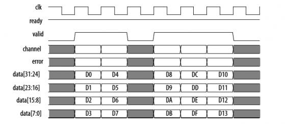
--- Quote Start --- Sampling streaming data is easy since it is synchronous to the clock. In an always block with the condition of posedge clk, you would check if your valid signal is asserted. Then you would read the data. --- Quote End --- So, from documentation I got only following instructions.http://www.alteraforum.com/forum/attachment.php?attachmentid=10729&stc=1 All transfers of an Avalon-ST connection occur synchronous to the rising edge of the associated clock signal. All outputs from a source interface to a sink interface, including the data, channel, and error signals, must be registered on the rising edge of clock. Inputs to a sink interface do not have to be registered. Registering signals at the source facilitates high frequency operation. I am not an experienced fpga developer, but an electronic engineer. From timing diagram it seems that I should sample data at falling edge. But from documentation and following your sugestion It seems right to sample data at rising edge and to registering outputs synchronously at rising edges. This last part seems not compliant to what you are suggesting for output data on the state machine. I don't understand if I am not following documentation or if there is a lack on it. Anyway official shared code from altera could provide the solution. Hope I am getting right :) Thank you Krasner.
- Mark as New
- Bookmark
- Subscribe
- Mute
- Subscribe to RSS Feed
- Permalink
- Report Inappropriate Content
Altera documentation is notoriously bad, at least in my experience. So try reading the latest versions of documentation.
Avalon streaming data is sampled on rising edge as is shown in your figure. Which part seems no compliant? Is it the FSM part? Seeing as you are trying to make a Moore state machine you would have 2 state (state1, state2) and transitioning between these states depends on your input X. To do this you need first sample your stream and store the value into reg X. Then your FSM would transition based on your X changing. The first part will be the same as before: wire [width-1:0] d; reg [width-1:0] X; assign d = data_in; always @(posedge clk) begin if (snk_valid) begin X<= d; end end Then we need to define the FSM: a) define state and next_state reg [1:0] state (since you have two states 01 and 10) reg [1:0] next_state parameter state1 = 2'b01; parameter state2 = 2b'10; (just assigning values to our state names) b) define how the FSM changes state. Here we use the combinatorial always block: always @( state or X) //our sensitivity list is state or X next_state = 0; case(state) //now we look at what state comes next state1: //lets say that if X = 0 then we keep the same state, if X = 1 we go to state2 begin if( X == 1 ) next_state = state2; else next_state = state1; end state2:// same idea for state2 if (X == 1) next_state = state1; else next_state = state2; end endcase end c) We defined next_state so we have to update state always @(posedge clk) begin state <=next_state end d)Now we define what to do when we are in each state. Since we are outputing an avalon stream we want this to be clocked and i guess in sync with the incoming valid signal reg dout; always @(posedge clk) //clocked process begin if (snk_valid) begin //sync signal to valid of input case(state) //again we will do a case statement for the states state1: dout <= "Some output" state2: dout <= "Some other output" default: dout< = 0; endcase end end -------------------------------------------------------------------------------------------------------------------------------------------------------------------------------------------------------------------------------------------- So you see we have 4 subsections: 1) sample incoming data 2) define transitions of FSM states 3) update current state 4) define functions during each state Let me know if these looks reasonable- Mark as New
- Bookmark
- Subscribe
- Mute
- Subscribe to RSS Feed
- Permalink
- Report Inappropriate Content
--- Quote Start --- So, from documentation I got only following instructions.http://www.alteraforum.com/forum/attachment.php?attachmentid=10729&stc=1 All transfers of an Avalon-ST connection occur synchronous to the rising edge of the associated clock signal. All outputs from a source interface to a sink interface, including the data, channel, and error signals, must be registered on the rising edge of clock. Inputs to a sink interface do not have to be registered. Registering signals at the source facilitates high frequency operation. I am not an experienced fpga developer, but an electronic engineer. From timing diagram it seems that I should sample data at falling edge. But from documentation and following your sugestion It seems right to sample data at rising edge and to registering outputs synchronously at rising edges. This last part seems not compliant to what you are suggesting for output data on the state machine. I don't understand if I am not following documentation or if there is a lack on it. Anyway official shared code from altera could provide the solution. Hope I am getting right :) Thank you Krasner. --- Quote End --- If you're doing things inside the the FPGA, on the same clock, for all logic you should be sampling on the rising edge of the clock. The timing analyser will tell you if there are any setup violations, which can then be fixed in your code, usually with more pipelining. The timing diagram you see is a digital logic waveform, not a fully timed interface specification, because it is not needed.
- Mark as New
- Bookmark
- Subscribe
- Mute
- Subscribe to RSS Feed
- Permalink
- Report Inappropriate Content
--- Quote Start --- Altera documentation is notoriously bad, at least in my experience. So try reading the latest versions of documentation. --- Quote End --- It is usally far better than Xilinx documentation!
- Mark as New
- Bookmark
- Subscribe
- Mute
- Subscribe to RSS Feed
- Permalink
- Report Inappropriate Content
Thankyou for your support! Definitely useful. It will be implemented soon.
Reply
Topic Options
- Subscribe to RSS Feed
- Mark Topic as New
- Mark Topic as Read
- Float this Topic for Current User
- Bookmark
- Subscribe
- Printer Friendly Page