- Mark as New
- Bookmark
- Subscribe
- Mute
- Subscribe to RSS Feed
- Permalink
- Report Inappropriate Content
Hi all,
I'm struggling with my understanding about Cyclone V transceivers in SX/GX devices. We have a custom board with 2 Cyclone V FPGAs. The one is an SX and the other one a GX device. They are connected via 2 transceiver lanes. I succesfully modified the Transceiver Toolkit example to get a testpattern communication between both devices in full duplex mode on both lanes. No errors occur (unless I inject one) and it runs stable over hours. So I'm pretty confident that the hardware is just okay..... Now, I would like to implement my own transceiver FPGA fabric logic. I tried to understand the test pattern generator and ckecker source code that drives the Toolkit examples. I implemented my own components in VHDL (because this is my preferred language) and I'm able to transmit data via the serial link. I used the same settings of the transceivers (in QSys) as in the toolkit examples. However, I really have troubles in understanding how I have to interpret the data that I get on the receive side of the transceiver link. The first naive step has been to send a 32 bit wide data word to the parallel tx data port of the native transceiver component and receive the same 32 bit word on the rx data port of the receiving native transceiver component...... That was completely not the case, so I digged more and found out that I probably have to use a 40 bit wide port on the transceiver components, because there is a gap of 2 bits for each 8 bit user data which are just not important, if I don't use 8b/10b encoding. So I put my user data that I would like to transmit (32bit) on the transmitter port in that way: tx_port(7 downto 0) <= data(7 downto 0); tx_port(17 downto 10) <= data(15 downto 8); tx_port(27 downto 20) <= data(23 downto 16); tx_port(37 downto 30) <= data(31 downto 24); After that, again, I was expecting that I receive something similar on the rx side that I send on the tx side.... which was not the case. It is not even so that the data is shifted because I may miss some word alignment, it is just somehow confused so that the data is not recognisable, at all..... Apropos word alignment.... since I set up (in QSys) the word alignment pattern equally on the tx and rx side, I suppose that I don't even have to care about word alignemnt because the trasceiver cores will handle that on their own. (is that correct?) Because I was not able to get my own transceiver link to work, I decided to signal tap the working toolkit examples. Unfortunately, confusion got even worse, because I see the same effects in my signal tap traces as with my custom components. The pattern that is send via the tx channel ist not received on the rx side. It is totally different. Nevertheless, the result in the system console GUI ist green and no errors are detetced. If I inject an error, it is recognized on the other side. So here is my basic transceiver misunderstanding: I think that the transceivers are implemented in the FPGAs in order to protect the user (or custom FPGA logic developer) from the need to understand all that transceiver stuff. I thought, I can just put a stream of data into the TX side, and get that same stream of data on the RX side. All the encodings, alignments, disparity checks, bit slippings and clock recoveries are done in the hard IP transceiver modules according to their settings.... Is there any explanation out there, step by step, of an innocent 32bit TX data word that is fed through this transceiver hell, which describes what happens to this data on its way throug all the different stages of the transceivers (TX and RX) and how it ist possible to get the same data back at the end of the transmission line? I read alot through the documentation (even XILINX docs I already read) but have not found the reason why the rx data word is so scrambled.....and most importantly, how I can de-scramble it. Basically, what I would like to have is, if the tx and rx transceiver are configured the same way, to get the data on the rx-port that I send on the tx-port. Please be kind with me if this is a totally stupid question, but I just don't know where to look anymore..... Thanks, MaikLink Copied
10 Replies
- Mark as New
- Bookmark
- Subscribe
- Mute
- Subscribe to RSS Feed
- Permalink
- Report Inappropriate Content
I would suggest that you start your design with simple transceiver setup. For example, single channel with fixed data pattern. Try to start with minimum data width first ie 8 bit. Simulation your design before trying on hardware.
- Mark as New
- Bookmark
- Subscribe
- Mute
- Subscribe to RSS Feed
- Permalink
- Report Inappropriate Content
Maybe to claryfy alittle bit why I'm so confused: This thread
http://www.alteraforum.com/forum/showthread.php?t=41766&highlight=transceiver (http://www.alteraforum.com/forum/showthread.php?t=41766&highlight=transceiver) mentions that there has to be done some word alignment in the HDL of my component which I just cannot believe .... but it seems as if that is the experience of some users. Additionally, it mentions that the simulation is working as expected but not the hardware..... That is why I try to get it working using signal tap (or at least gain some experience). Yesterday, I was able to actually see (by signal tapping the transceiver toolkit design an using loopback mode on the SX FPGA) that the PRBS7 pattern which I send on the TX side indeed gets received on the RX side. What I still wonder is this: I start sending the test pattern by clicking on start in the Transceiver Toolkit GUI (in the "transceiver link" tab, because I would like to use the serial loopback mode). I provided the synchronisation_question screenshot, where it is shown, when the transmission of a PRBS7 code is started. The first word send of this code is 0x020C28F22C. I triggered on that sequence on the RX Avalon ST input of the pattern checker component. It first appears after about 180 (blue questionmark) data words of useless(???) data. So I wonder, why is there so much useless data at the beginning on the RX side? Is it because the clock recovery of the RX PHY has to gather enough information in order to determine the correct clock for data de-serialization? The next thing is that after the first occurance of the PRBS7 data start word, there is still a huge gap without the data beeing vaild (asi_valid -> low, green questionmark). I know from other signal tap shots, that the asi_valid signal becomes valid after some time and therefor, I suppose I do not have errors on my transmission line in the Transceiver Toolkit. And after that I know, it is working very well, because I never see any errors even after hours..... I really just wonder, why it takes so long to get this asi_valid signal active? Is this a fixed time? Depending on what? What if I don't want to use this transceiver link to constantly send a stream of data but e.g. just 256 32 bit words every ms. I just want that to be very quick (and therefore use the transceiver link). But when I have to wait for so many clock cycles to get that asi_valid signal active, how can I know on the transmit side, that my data actually reached the destination? I know, I could use a very complicated protocol for that that detects packet loss, etc. But what would be the simplest method to do so? I just need a communication between the FPGAs as described above: every ms I would like to transmit a certain amount of data. I would like the data to be correctly received from the very first word on (not like in the screenshot example above). I think , I have to constantly transmit some kind of IDLE pattern like 0x55555555 and, when my user data should be send just put that into the stream instead of the IDLE pattern, right? Is this the way to go? Okay, I will wait for (hopefully) some answers on that in order to discuss this further if somebody is willing to help me improve my understanding. Thanks, Maik
- Mark as New
- Bookmark
- Subscribe
- Mute
- Subscribe to RSS Feed
- Permalink
- Report Inappropriate Content
Hi,
I think I really have an alignment problem and I don't know how to solve this. Here are the steps I did and the results I got: I send an idle sequence from my custom component to the TX streaming interface of the xcvr custom phy. I monitor that in signal tap and see that I do not receive anything on the rx side which is fine because I have not connected an external data source, yet. The next thing I do is to switch the serial loopback of the transceiver channel on. The result is that I now see my idle pattern at the streaming output of the xcvr custom phy. Because my idle pattern is 0x55555555, everything looks really good. Now, as soon as I send data e.g. a sequence of 0xffffffff words, I can see that this sequence goes to the tx port of the xcvr custom phy and a moment later, I receive "something" on the loopback rx path. This something is almost my 0xffffffff pattern but it is shifted one symbol (8bit) and so the first 0xffffffff sequence I should receive instead has a symbol of my idle or preamble sequenece in it. After my data block is completely transmitted, I again have one symbol shift in my data stream because the idle data also suffers from the above mentioned problem. I suppose that this effect is caused due to a not functioning word alignment. I have set up the word alignment in my custom xcvr phy just as in the transceiver toolkit example (pattern length 20; pattern "11111001111111111010"). And I believe that the transceiver toolkit example also uses an "FPGA fabric transceiver interface Width" of 40, just as my design. I read in the documentation that I have to set the rx_enapatternalign flag to 1 in order to get the word alignment working. I did that but it has no effect on the word alignment. I suppose that the xcvr core somehow "knows" that the rx data is not correct because I do not get an asi_valid flag. But, since I have this idle pattern running all the time, when I do not transmit my user block data, I was hoping that this is enough time to a) perform clock recovery and b) perform word alignment when the rx_enapatternalign flag is set. But unfortunatley, it is not working as I intend it to do. I attached a screenshot of a signal tap trace. It shows the idle pattern, my preamble pattern (0xaaaaaaaa) and the aformentioned user data block (0xffffffff). Finally, the idle pattern is transmitted, again. The red arrows mark where the errors occurs due to the missing word alignment. The exclamation mark value shows that the user data block still contains a symbol from the preamble block. The blue arrors show, that those basic patterns are generally transferred in a plausible manner. Just one remark. I always say, I use the patterns 0x55555555, 0xaaaaaaaa and 0xffffffff, but they look so different on the aso_data and asi_data signals. That is because I used the 32bit to 40bit scheme I described in the first post of this thread. Maybe somebody can tell me, if it is correct to do it that way, or if I misunderstood the description of the xcvr custom phy tx_data and rx_data description in the according Altera documentation. Thanks, Maik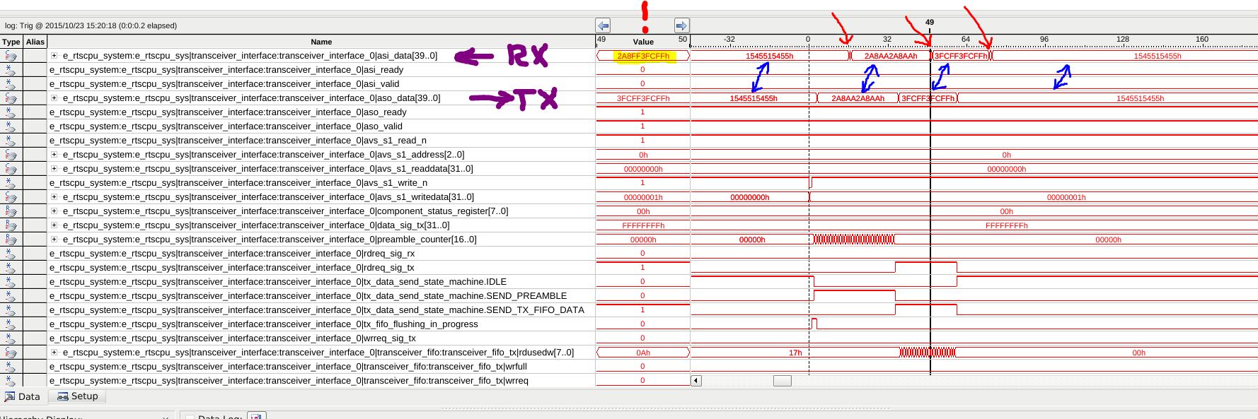
- Mark as New
- Bookmark
- Subscribe
- Mute
- Subscribe to RSS Feed
- Permalink
- Report Inappropriate Content
Hi Maik,
Given that you control both ends of the link, why not try using a component that already has alignment working? I believe the Altera SerialLite II component is designed for this. Xilinx used to have one called Aurora. I am sure there is an open-source equivalent. Altera SerialLite II: https://www.altera.com/solutions/technology/transceiver/protocols/pro-seriallite.html Xilinx Aurora: http://www.xilinx.com/products/design_resources/conn_central/grouping/aurora.htm http://www.xilinx.com/products/intellectual-property/aurora8b10b.html (http://www.xilinx.com/products/design_resources/conn_central/grouping/aurora.htm) The 'easiest' way to send data over a serial link is to encode the data using 8/10B. This has the dual feature of ensuring the data can be transported across AC coupled links (ensuring the signal toggles enough to have an average DC of zero), and the data stream has 'patterns' that the receiving end uses to align and recover the bytes in the serial data stream. Keep this in mind: you start with bytes, the transmitter serializes them, the receiver deserializes them, and you get some bytes at the output. Without some way to tell the receiver when to start converting bits to bytes, the data will come out misaligned. Stop trying to debug using SignalTap. Create a Modelsim simulation. You can probably start with the transceiver examples I posted here: https://www.ovro.caltech.edu/~dwh/correlator/cobra_docs.html Cheers, Dave- Mark as New
- Bookmark
- Subscribe
- Mute
- Subscribe to RSS Feed
- Permalink
- Report Inappropriate Content
Hi Dave,
thanks, again! I will have a deeper look into your advise. With your explanations from here http://www.alteraforum.com/forum/showthread.php?t=34787&page=10 (http://www.alteraforum.com/forum/showthread.php?t=34787&page=10) I'm pretty confident that I now can focus on my design again, or can have a look at some open cores that may already implement, what I'm looking for. Anyway, again, without your help, I would spend a lot more days to examine the TTK examples without realizing that there is nothing more to discover for me.... Regards, Maik- Mark as New
- Bookmark
- Subscribe
- Mute
- Subscribe to RSS Feed
- Permalink
- Report Inappropriate Content
--- Quote Start --- Anyway, again, without your help, I would spend a lot more days to examine the TTK examples without realizing that there is nothing more to discover for me.... --- Quote End --- No sense in us both reading through the code and realizing that it doesn't really do much ... and is poorly documented ... is buggy ... is incomplete ... Just read the Altera TTK Examples review: https://www.ovro.caltech.edu/~dwh/correlator/pdf/altera_ttk_examples.pdf Altera's response to my questions about the Stratix IV series issues was pretty much "Stratix IV devices are not supported in Qsys" ... my response "Why then do you have Stratix IV Qsys examples for the TTK?" ... response was ... silence ... :) Cheers, Dave
- Mark as New
- Bookmark
- Subscribe
- Mute
- Subscribe to RSS Feed
- Permalink
- Report Inappropriate Content
Hi Maik,
I agree with Dave. The is very little documentation on the TTK and it is also very buggy especially when you try to custimize the design example to your board. It is recommended to read Dave's review doc, it is very helpful.- Mark as New
- Bookmark
- Subscribe
- Mute
- Subscribe to RSS Feed
- Permalink
- Report Inappropriate Content
Hi,
I was able to succesfully implement the word alignemnt in my simulation project (yes, I went from Signal Tap to simulation.....). I started (as suggested) by implementing an 8 bit word transmission, went to 16 bit and now, I have my 32 bit word transmission with bit slipping word alignment running. I thought, that now I am able to just start the transmission of my user data in between the 32 bit sequence I use for word alignment. In order to test this, I started to transmit increasing counter values that initially starts at 0x0e0f0000. So I am able to see if all 32 bits are transferred correctly. so the sequence would be 0x0e0f0000 0x0e0f0001 0x0e0f0002 0x0e0f0003 0x0e0f0004 0x0e0f0005 ..... So the complete data stream I provide to the tx side is like this: ...... 0xaa5533ff 0xaa5533ff | 0xaa5533ff | 0xaa5533ff > used during word alignemnt with bit slipping 0xaa5533ff | 0xaa5533ff | 0xaa5533ff / <----- word alignment on rx side finished, pattern on RX received as send by TX. 0x0e0f0000 <---- Counter Squence starts on TX side. 0x0e0f0001 0x0e0f0002 0x0e0f0003 0x0e0f0004 0x0e0f0005 ..... Now, the problem is that in between the succesfull word alignment and the first correctly received counter pattern word, I get something like this on the RX side: 0xf54a533f 0xf54aa67f | 0xea95a67f | 0xea954cff > word alignemnt with bitslipping on RX side 0xd52a4cff | 0xd52a99ff | 0xaa5533ff / <--- word alignment pattern found, bit slipping stopped 0x0e0f33ff <----- would have expected that I receive the 32 bit counter sequence put into the TX side. Where is this pattern coming from? 0x0e0f0000 <----- from here on, everything seems to be correct 0x0e0f0001 0x0e0f0002 0x0e0f0003 .... So, I hope you see what my problem is and what the question will be: How can I avoid this "additional"(???) data? Do I need something like "byte ordering"?. If yes, why would I need this? My (mis-)understanding is that I must be fine after word alignment is finished sucessfully because the parallel data I send on the TX side is serialized, received on the rx side, bit slipped into the correct word boundaries and that's it. If no more bit slipping is aplied, the serialized data stream from the TX side should just come ot of the parallel rx side in the correct manner. The next thing is, that I don't really understand the importance of byte ordering (especially in this case). Can somebody explain, why it would be necessarry? I've read the Altera documentation and have seen the examples, but with my explanation from above I don't see the reason for byte ordering once the word alignment hase been successfully performed. I attached the modelsim waveform which shoes the word alignment process. The marker is placed at the questionable data word reception. (by the way, maybe somebody can answer why the tx_ready and rx_ready signals become 'X' once they should be '1'....) Edit: Okay, I think, maybe I have also a missunderstanding in the way, a 32 bit word is transferred over the transceiver link. What I have: 32 bit parallel data port FPGA fabric ransceiver interface width. 16 bit PCS-PMA interface width. I read in the documentation that the least significant 16 bit word (LSBW) of my 32 bit user data is transmitted first and after that the most significant 16 bit word (MSBW) of my 32 bit user data is transferred. Because of this, I suppose that the TX-LSBW ends up in the RX-MSBW and the TX-MSBW goes into the RX-LSBW. Is that assumption correct? I think, it has to be that way, because otherwise (TX-LSBW -> RX-LSBW, TX-MSBW -> RX-MSBW), I was not able to get mey word alignment correct with bitslipping. Now, I wonder if maybe I have an error already here because when I send user data, it appears that I always have MSBW of the next 32bit value mixed up with the LSBW of the currently expected 32bit data word. Again, I have the question, if there is a very simple example available, where I can just put in 32 bit user data on one side and get the same 32 bit data out of the other side. I'm really struggeling a lot and can just not figure out how this would work for the very simple transmission I want to realize..... Thanks, Maik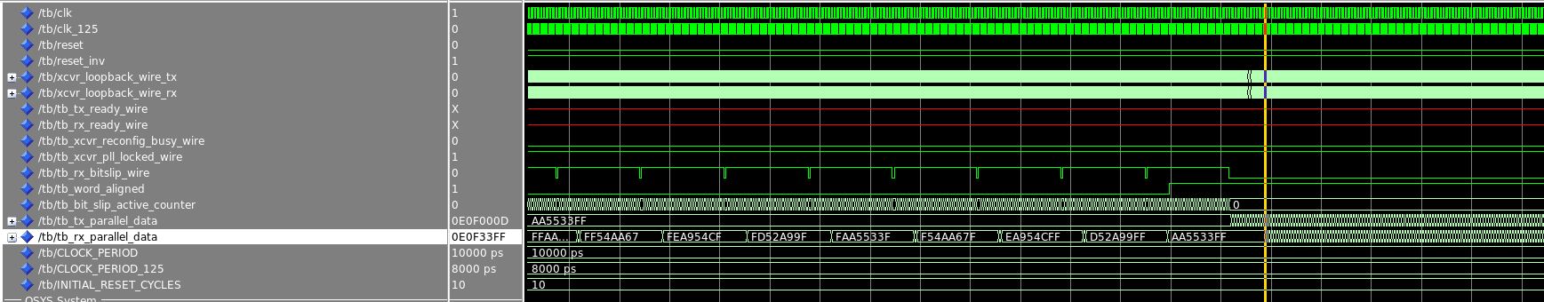
- Mark as New
- Bookmark
- Subscribe
- Mute
- Subscribe to RSS Feed
- Permalink
- Report Inappropriate Content
Hi Maik,
You need to learn to write more concise requests for help. No one will read a really long post. Rather than post a screen shot, post code, and a script that will run the code. I cannot tell from your description if you are using the 8/10B encoder. If you are not, then your data *MUST* have lots of toggles embedded in it to ensure the clock-and-data recovery (CDR) in the receiver stays locked to the data. Sending across a count would not meet this requirement ... it might work in simulation ... but not in the real-world. If you were using 8/10B encoding, then most of the synchronization should already be done for you ... or you should just use the SerialLiteII core until you have that working ... Cheers, Dave- Mark as New
- Bookmark
- Subscribe
- Mute
- Subscribe to RSS Feed
- Permalink
- Report Inappropriate Content
Hi Dave,
you are right.... maybe too much text. I attached the system I'm simulating on. You need to generate the qsys file into a subfolder called e_rtscpu_sx and then run "source run_simulation.tcl" in modelsim. It should start a 50us simulation, where the alignment is performed and after that "user data" is transferred. In the 16bit (FPGA to XCVR interface) version, everything works as expected. In the 32bit version, I get the above mentioned issue and alignment only works when I switch the received 16 LSB to MSB and vice versa. You are right, in practice, I may need additional encoding, but I first would like to get the bit slipping alignment to work and would like to test that also in HW. Just out of curiosity.... Regards, Maik
Reply
Topic Options
- Subscribe to RSS Feed
- Mark Topic as New
- Mark Topic as Read
- Float this Topic for Current User
- Bookmark
- Subscribe
- Printer Friendly Page