- Mark as New
- Bookmark
- Subscribe
- Mute
- Subscribe to RSS Feed
- Permalink
- Report Inappropriate Content
Hi, I was required to build a decimation filter using FIR filter (CIC filter cannot be used). I used FIR compiler to implement the decimation filter. The sampling frequency of ADC is 120 MHz, and I need the output sample rate is 2.5 MHz. I build the system as two cascade decimation FIR filters, where the first one has the decimation factor of 12 and the following one has the decimation factor of 4. The filter seems to work. However, there is spurious signals in the spectrum of the output. This happens for some input frequencies, not all. I don't know what the problem is. Neither I know how to fix it. Any one has some suggestion? Thank you very much in advance!
Link Copied
- Mark as New
- Bookmark
- Subscribe
- Mute
- Subscribe to RSS Feed
- Permalink
- Report Inappropriate Content
assuming the cutoff is adequate then a possible area to cause spur is overflow of output data in your filter leading to wrapping up of results.
your cutoff must be at least 0.5*1/48 of 120MHz = 1.25MHz- Mark as New
- Bookmark
- Subscribe
- Mute
- Subscribe to RSS Feed
- Permalink
- Report Inappropriate Content
Thanks, kaz. You mean the least cutoff freq should be no less than 1.25 MHz. If I would like to have the cutoff freq to be 1 MHz, then I should have another single rate FIR filter in the following. Is that right?
Does the requirement for cutoff freq also suit for the 1st decimation fir? I mean the cutoff freq for the 1st decimation FIR should also be no less than 1.25 MHz?- Mark as New
- Bookmark
- Subscribe
- Mute
- Subscribe to RSS Feed
- Permalink
- Report Inappropriate Content
Good point.
The first filter samples at 120Mhz but outputs at 10MHz, hence must cutoff at 5Mhz. The second filter samples at 10 MHz and outputs at 2.5MHz, hence must cut off at 1.25MHz any cut off below that is only correct if your signal doesn't include that range of frequency otherwise you cut your signal off. make sure the cutoff is entered correctly: for 1st filter = 5/120 for 2nd filter = 1.25/10- Mark as New
- Bookmark
- Subscribe
- Mute
- Subscribe to RSS Feed
- Permalink
- Report Inappropriate Content
I have limited the cutoff freq to satisfy the decimation requirements (<=5MHz for 1st, and <=1.25MHz for 2nd). Actually, I let both of them be 1 MHz. Now, I used a mixer before the decimation FIR filters. The input to the filters include two frequencies; i.e.,fi+fc and fi-fc, where fc is the center frequency of the tuner and fi is the input frequency. I'd like to have the fi-fc and remove fi+fc, but the result still wraps up. I'm very confused about this.
The attached figure is the spectrum of the output from the 1st filter. In this experiment, the input frequency is 25.58MHz, and the tuning center frequency is 24.98MHz. We can the desired frequency 0.6MHz, but we can also see the spurious signal -0.56MHz which is the wrapped up from the signal of -50.56MHz. Thanks a lot for any comments and help!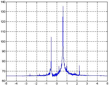
- Mark as New
- Bookmark
- Subscribe
- Mute
- Subscribe to RSS Feed
- Permalink
- Report Inappropriate Content
check your mixer is working. Or use one frequency at a time.
After that check that your filter is cutting off as required and with enough stop band attenuation. I also notice that your spectrum is not symmetrical. Are dealing with a complex signal?- Mark as New
- Bookmark
- Subscribe
- Mute
- Subscribe to RSS Feed
- Permalink
- Report Inappropriate Content
I have checked the mixer, and it works well. I also use the single tone for test and have the same problem. Yes, I use I and Q to have a complex signal at baseband.
The following attachments are the responses of two decimation FIR filters. I exports the coefficients of the filters and plot the spectrum using MATLAB. The figures seem to show that the filter work well. I also simulate input signal in MATLAB to see the results. It has no problem. But the implementation in FPGA will give me such wired results. I have no idea about this issue.- Mark as New
- Bookmark
- Subscribe
- Mute
- Subscribe to RSS Feed
- Permalink
- Report Inappropriate Content
It is best to model your case in Matlab e.g.(for -25MHz/26MHz):
x1 = exp(j*2*pi*(0:2^20-1)*-25/120); %complex sinusoid x2 = exp(j*2*pi*(0:2^20-1)*26/120); %complex sinusoid x = x1.*x2 %mixer h = fir1(200,40/60); %or choose any other better cutoff as your filter y = upfirdn(x,h,1,48) %apply filter/decimation plot(20*log10(fftshift(abs(fft(y))))); %fft- Mark as New
- Bookmark
- Subscribe
- Mute
- Subscribe to RSS Feed
- Permalink
- Report Inappropriate Content
The problem seems that the FIR compiler implement downsampling before filtering. I use the same coefficients but let filters be single rate. Then I downsample the filter output by myself. I can get the right results. I'm wondering whether there is something wrong when I use FIR compiler to implement decimation filter.
- Mark as New
- Bookmark
- Subscribe
- Mute
- Subscribe to RSS Feed
- Permalink
- Report Inappropriate Content
You can apply single rate filter then do decimation directly provided you cut off at the right frequency relative to your signal spectrum edge.
Additionally you can apply the same filter in a decimation polyphase structure. In your case you will have 48 polyphases and will need tap/48 multipliers only.- Mark as New
- Bookmark
- Subscribe
- Mute
- Subscribe to RSS Feed
- Permalink
- Report Inappropriate Content
Thank you, kaz! The way that applies single rate filter by using FIR compiler and does decimation following works correctly. But using FIR compiler to implement decimation filter still doesn't work. I try to find relative errata about FIR compiler but find nothing.
That's great! The decimation polyphase structure could reduce resources. I'm not very clear about how to implement decimation filter in polyphase structure. Is that right to divide coefficients into several groups and apply them to the corresponding filters by using FIR compiler?- Mark as New
- Bookmark
- Subscribe
- Mute
- Subscribe to RSS Feed
- Permalink
- Report Inappropriate Content
The decimation polyphase structure consists of a delay line of length = taps.
The taps are split into 48 groups e.g. if you have 48*3 taps(main filter) then polyphases are: p1 = 1:48:end p2 = 2:48:end ...etc p48 =48:48:end the multipliers are wired every 48 delay stages. Those in between are left as pipe only. The output is updated at the slow clock(2.5MHz) by accumulating the results of 48 polyphases. The coefficients take turns at the multiplier and you should use the correct order. It is in effect a TDM based structure since output is slower than input 48 times. There is plenty of literature around. I know altera got an example vhdl somewhere...- Subscribe to RSS Feed
- Mark Topic as New
- Mark Topic as Read
- Float this Topic for Current User
- Bookmark
- Subscribe
- Printer Friendly Page