- Mark as New
- Bookmark
- Subscribe
- Mute
- Subscribe to RSS Feed
- Permalink
- Report Inappropriate Content
Hi,
I am performing some experiment with S-10 SoC Dev kit (L-tile).
I am using FMC loopback cards to check the behavior of SERDES so as to use for my final requirement.
My goal is to connect a device with FPGA through Transceiver lines. My target device is characterized to have 85-ohm trace impedance, but, FPGA board is routed with 100-ohm (or 95-ohm as per board file). But, I do not have my target device ready as of now.
So, I have done one experiment with available SoC dev kit and FMC loopback card.
By default, the TX and RX terminations will be 100-ohm and with this I am seeing good eye opening and BER is zero in Transceiver toolkit.
So I did 4 different experiment and I am seeing no eye opening if I configure TX to 85 ohm.
Can you comment on this behavior? Or there is any other way to improve on this error cases?
Across all the tests, below configuration is maintained.
VOD = 31, pre-emphasis pre & post tap = 0, PRBS7
RX Side, adaptive mode with DFE all tap adaptive
Refer to the attached snapshots
Case 1 ) Tx & RX - 100-Ohm termination - BER = 0, PRBS7_Rx100_TX100_Eye_38_113.png
case 2) TX 100 ohm, RX 85- ohm, BER = 0, PRBS7_Rx85_TX100_45_73.png
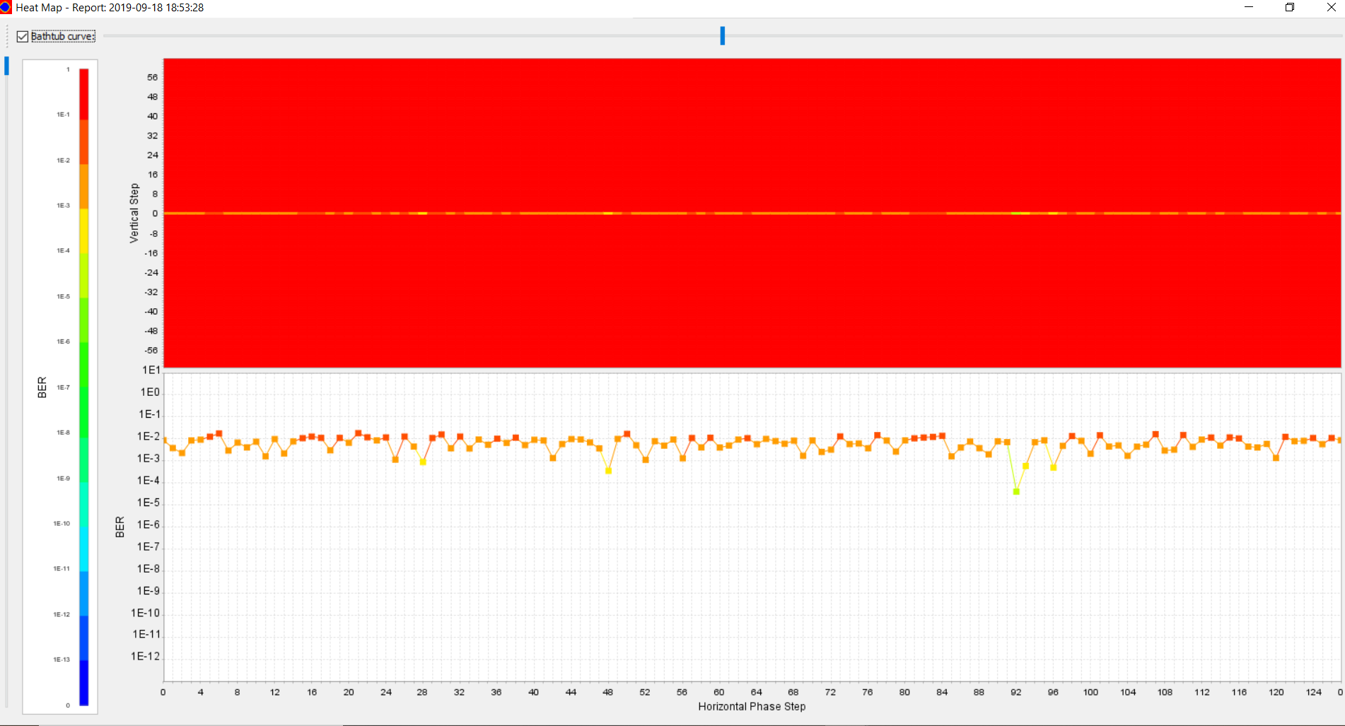
case 3 ) TX-85 ohm, RX- 100 ohm, BER = 10^-3, PRBS7_Tx85_RX100_no_eye.png
case 4 ) TX-85 ohm, RX- 85 ohm, BER = 10^-3, PRBS7_Tx85_RX85_no_eye.png
With regards,
HPB
Link Copied
- Mark as New
- Bookmark
- Subscribe
- Mute
- Subscribe to RSS Feed
- Permalink
- Report Inappropriate Content
Hi HPB,
As I understand it, you seems to observe high BER when you are using TX output impedance 85 Ohm which is mismatching with the board trace of 100 Ohm. For your information, since there are impedance mismatch, I believe the high BER is due to the signal integrity issue. Generally it is recommended to use matching impedance.
You may try to run auto-sweep in TTK with different PMA analog settings to see if any of the combination can help for the failing case.
Please let me know if there is any concern. Thank you.
Best regards,
Chee Pin
- Mark as New
- Bookmark
- Subscribe
- Mute
- Subscribe to RSS Feed
- Permalink
- Report Inappropriate Content
Hi Chee Pin,
<As I understand it, you seems to observe high BER when you are using TX output impedance 85 Ohm which is mismatching with the board trace of 100 Ohm.>
Yes, you are right.
Regarding Auto sweep, I did perform it and unable to get any best result with acceptable BER for failing cases. (Auto sweep for entire range of 0 to 31, with negative to positive boundary of pre-emphasis taps).
Here, when I constraint only RX to 85-Ohm, then there is a good eye opening. In both the failing cases, TX is constrained to 85-ohm.
So, I want to know, whether any Tx side configuration is there apart from VOD, pre-emphasis settings which I need to take care to transmit the signals with good integrity.
With Regards,
HPB
- Mark as New
- Bookmark
- Subscribe
- Mute
- Subscribe to RSS Feed
- Permalink
- Report Inappropriate Content
Hi HPB,
Regarding the TX analog settings, apart from the VOD and pre-emphasis, there is another parameter - slew rate control. However, based on my understanding, generally VOD and pre-emphasis would have more significant impact to signal integrity. In your case, I think you would need to look into using matching impedance since the auto-sweep is unable to get any acceptable BER for you. Sorry for the inconvenience.
Please let me know if there is any concern. Thank you.
Best regards,
Chee Pin
- Mark as New
- Bookmark
- Subscribe
- Mute
- Subscribe to RSS Feed
- Permalink
- Report Inappropriate Content
Hi Chee Pin,
Thank you for hinting towards slew rate. Let me check that as well.
I think this is one of the aspect which I missed. In all my previous tests, Slew rate control was set to '0'. Just now I gone through the XCVR user guide and found that Slew rate control is set o 5 for Gen2 PIPE and Gen3 PIPE.
Also, I want to know the definition of values of slew rate control ( 0 to 5). i.e. what is the meaning of slew rate control = 0, 1 etc..
With regards,
HPB
- Mark as New
- Bookmark
- Subscribe
- Mute
- Subscribe to RSS Feed
- Permalink
- Report Inappropriate Content
- Mark as New
- Bookmark
- Subscribe
- Mute
- Subscribe to RSS Feed
- Permalink
- Report Inappropriate Content
Hi,
Regarding the slew rate control settings, as I understand it from the user guide, 0 = slowest and 5 = fastest. There seems to be no specific specs in term of seconds in the user guide.
Thank you.
Best regards,
Chee Pin
- Mark as New
- Bookmark
- Subscribe
- Mute
- Subscribe to RSS Feed
- Permalink
- Report Inappropriate Content
Hi,
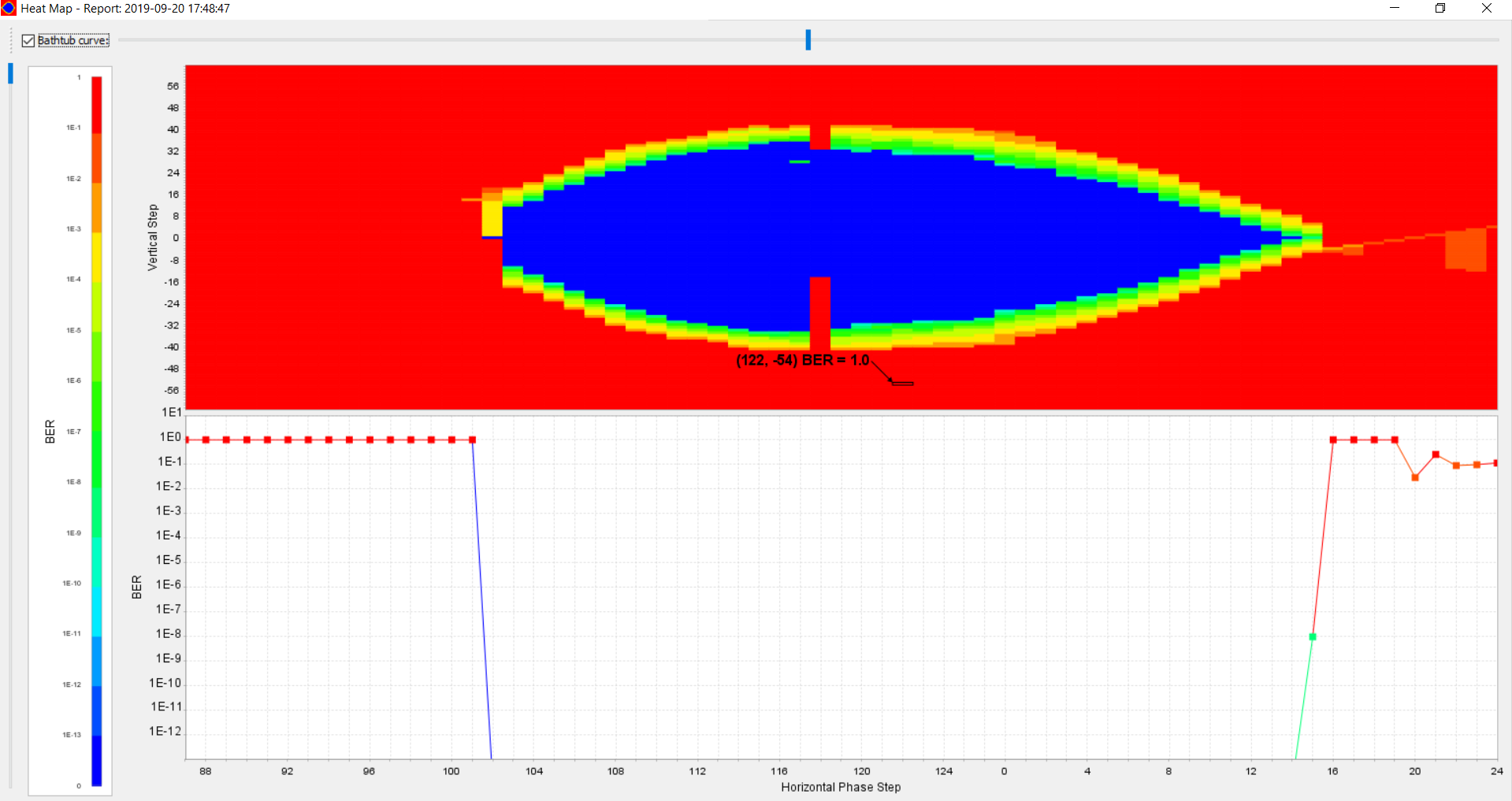
I carried out the experiment with TX& RX termination set to 85 ohm and Slew rate control = 5. With this I am seeing the eye opening.
attached the snapshot of the same. Eye is captured with PRBS7. Also, I checked the BER for PRBS31 by transmitting around 10^12 bits, but BER remained 0 in the TTK.
With regards,
HPB
- Mark as New
- Bookmark
- Subscribe
- Mute
- Subscribe to RSS Feed
- Permalink
- Report Inappropriate Content
Hi HPB,
Thanks for your update. Glad to hear that by setting the slew rate to the highest is helping to improve the BER in your board setup. I understand that the existing impedance mismatch is due to the devkit trace impedance. Please note that in your final board implementation, it is still recommended ensure impedance matching with trace impedance and TX/RX OCT.
Thank you.
- Mark as New
- Bookmark
- Subscribe
- Mute
- Subscribe to RSS Feed
- Permalink
- Report Inappropriate Content
Hi,
<Glad to hear that by setting the slew rate to the highest is helping to improve the BER in your board setup>
This is Stratix 10 SoC Dev kit (L-tile ) and FMC loopback card setup
<Please note that in your final board implementation, it is still recommended ensure impedance matching with trace impedance and TX/RX OCT>
Yes. It is understood clearly.
Thank you..
With regards,
HPB
- Subscribe to RSS Feed
- Mark Topic as New
- Mark Topic as Read
- Float this Topic for Current User
- Bookmark
- Subscribe
- Printer Friendly Page